Hello again,
A correct understanding of a problem should allow a hypothetical >identification of a faulty component. Replacement of the component
allowing the machine to work tends to support correctness of the >understanding.
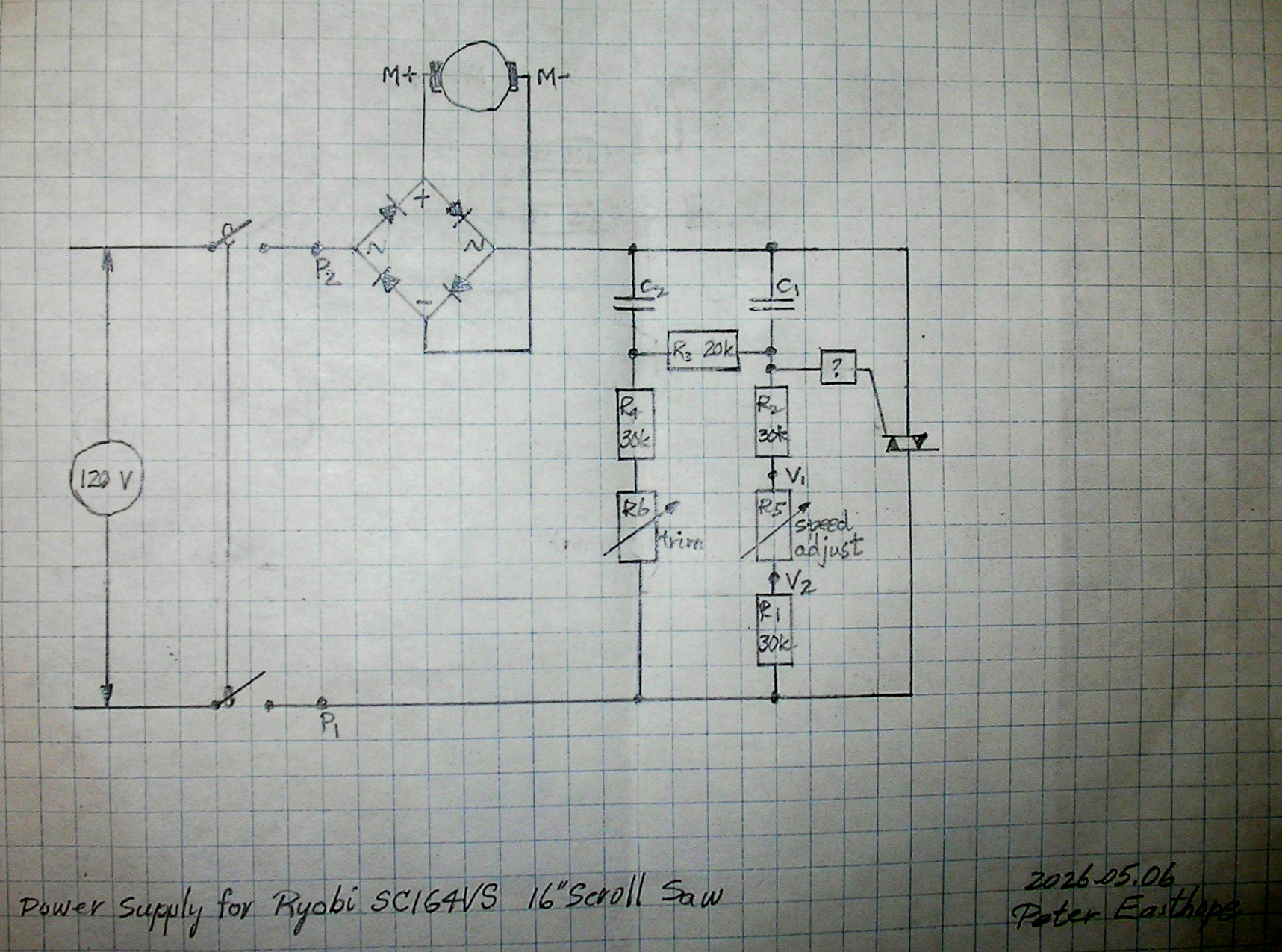
My schematic is here.
https://easthope.ca/RyobiScrollSawSC164VSboard.jpg
In my previous hasty efforts, replaced the diode bridge, the triac and
the speed adust pot.
I think of two simple tests.
Make the circuit board accessible and connect the power plug to a
variac, initially powered off.
(1) Jumper the two terminals (not the gate) of the triac and supply 10
to 15 V with the variac. If the motor turns, it's probably OK.
Remove the jumper.
(2) Jumper across the diac, marked ? in the schematic, and supply 10
to 15 V with the variac. If the motor turns, the failure is probably
in the diac. Replace the diac an check whether the machine works.
Any warnings before I blunder further?
Thx, ... P.
Hello again,
A correct understanding of a problem should allow a hypothetical identification of a faulty component. Replacement of the component
allowing the machine to work tends to support correctness of the understanding.
My schematic is here.
https://easthope.ca/RyobiScrollSawSC164VSboard.jpg
In my previous hasty efforts, replaced the diode bridge, the triac and
the speed adust pot.
I think of two simple tests.
Make the circuit board accessible and connect the power plug to a
variac, initially powered off.
(1) Jumper the two terminals (not the gate) of the triac and supply 10
to 15 V with the variac. If the motor turns, it's probably OK.
Remove the jumper.
(2) Jumper across the diac, marked ? in the schematic, and supply 10
to 15 V with the variac. If the motor turns, the failure is probably
in the diac. Replace the diac an check whether the machine works.
Any warnings before I blunder further?
Thx, ... P.
Instead, I would use 120 VAC input. With the triac shorted
MT1 to MT2, the motor should spin at full speed. If not,
a bad motor or bad bridge or bad wiring/connection.
If the motor spins at full speed, the triac circuit is failing,
most likely the triac or the diac.
You can use your ohm meter
to check the resistors and and a cap tester for the caps.
For all of the above your hands and test equipment will not be--
in the device when 120VAC is applied, so it's safe for you. Shorting
the triac wont hurt the equipment during tests.
On Tue, 19 May 2026 21:51:07 -0400, ehsjr <ehsjr@verizon.net> wrote:
Instead, I would use 120 VAC input. With the triac shorted
MT1 to MT2, the motor should spin at full speed. If not,
a bad motor or bad bridge or bad wiring/connection.
Do you test an automobile engine, chainsaw, or other speed controlled
devices by "flooring" the throttle or speed control to maximum, and
then applying power? Do you fix a hi-fi audio system with the volume >controls at full blast? That's exactly what you're doing by shorting
the triac. Methinks a better idea would be to leave the triacs and
wiring in place, and replace the scroll saw motor with an incandescent
light bulb.
Incidentally, please note that my domain name is
"LearnByDestroying.com". There's a reason for that name, which I
don't want to discuss at this time (dinner will soon be cold). Let's
just say that I learned from experience that spectacular methods of >self-education are effective, but usually not the best path toward >enlightenment.
If the motor spins at full speed, the triac circuit is failing,
most likely the triac or the diac.
If you used that method to test an automobile engine or chainsaw, a >successful test would be the self-disassembly of the engine after it
exceeds the maximum RPM limit. Incidentally, excessive RPM is a
problem with engine and chainsaw repair, as well as other devices with
an adjustable speed (RPM) control. Maximum control position could
easily be higher than maximum safe RPM if the operating RPM requires
that the device be under load or if some creative engineer is using
some kind of rotation limiter on the control positition as a
mechanical maximum RPM limiter.
You can use your ohm meter
to check the resistors and and a cap tester for the caps.
Ummm, most low end ESR (equivalent series resistance) capacitor
testers at designed to test at 100 kHz. There are a few that will
test at 60 Hz, but those are not common. In most cases, if the cap
tester shows acceptable ESR at 100 kHz, it also be acceptable at 60
Hz. However, I've been suprised by some situations where the test
frequency does matter. ><https://passive-components.eu/why-low-esr-matters-in-capacitor-design/>
Ummm, most low end ESR (equivalent series resistance) capacitor
testers at designed to test at 100 kHz. There are a few that will
test at 60 Hz, but those are not common. In most cases, if the cap
tester shows acceptable ESR at 100 kHz, it also be acceptable at 60
Hz. However, I've been suprised by some situations where the test >>frequency does matter. >><https://passive-components.eu/why-low-esr-matters-in-capacitor-design/>
On the graph, notice the variations in ESR with frequency for an MLCC
X7R capacitor.
On Tue, 19 May 2026 21:51:07 -0400, ehsjr <ehsjr@verizon.net> wrote:
Instead, I would use 120 VAC input. With the triac shorted
MT1 to MT2, the motor should spin at full speed. If not,
a bad motor or bad bridge or bad wiring/connection.
Do you test an automobile engine, chainsaw, or other speed controlled
devices by "flooring" the throttle or speed control to maximum, and
then applying power? Do you fix a hi-fi audio system with the volume controls at full blast?
That's exactly what you're doing by shorting
the triac.
Methinks a better idea would be to leave the triacs and
wiring in place, and replace the scroll saw motor with an incandescent
light bulb.
Incidentally, please note that my domain name is
"LearnByDestroying.com". There's a reason for that name, which I
don't want to discuss at this time (dinner will soon be cold). Let's
just say that I learned from experience that spectacular methods of self-education are effective, but usually not the best path toward enlightenment.
If the motor spins at full speed, the triac circuit is failing,
most likely the triac or the diac.
If you used that method to test an automobile engine or chainsaw, a successful test would be the self-disassembly of the engine after it
exceeds the maximum RPM limit.
Incidentally, excessive RPM is a
problem with engine and chainsaw repair, as well as other devices with
an adjustable speed (RPM) control. Maximum control position could
easily be higher than maximum safe RPM if the operating RPM requires
that the device be under load or if some creative engineer is using
some kind of rotation limiter on the control positition as a
mechanical maximum RPM limiter.
You can use your ohm meter
to check the resistors and and a cap tester for the caps.
Ummm, most low end ESR (equivalent series resistance) capacitor
testers at designed to test at 100 kHz. There are a few that will
test at 60 Hz, but those are not common. In most cases, if the cap
tester shows acceptable ESR at 100 kHz, it also be acceptable at 60
Hz. However, I've been suprised by some situations where the test
frequency does matter. <https://passive-components.eu/why-low-esr-matters-in-capacitor-design/>
For all of the above your hands and test equipment will not be
in the device when 120VAC is applied, so it's safe for you. Shorting
the triac wont hurt the equipment during tests.
Those caps are too small in value. You're not going to find a bad cap
in his circuit with an esr meter. A capacitance meter will show an open
cap if its open.
On Wed, 20 May 2026 12:59:50 -0400, ehsjr <ehsjr@verizon.net> wrote:
Those caps are too small in value. You're not going to find a bad cap
in his circuit with an esr meter. A capacitance meter will show an open
cap if its open.
Where did you find the values of the capacitors?
I couldn't see the
values in the video:
"Ryobi Scroll Saw Fix"
<https://www.youtube.com/watch?v=ADyM5x1cZQ4>
and they're not mentioned in Peter's postings.
Looking at the caps in the video, they look like metallized
polypropylene film capacitors. I would guess 0.1 uF for both caps.
You're probably right that 0.1 uF is too small for a valid ESR test.
Instead of a Variac, a "dim light bulb tester" in series with the
power line is good enough to prevent motor overspeed. I have several: <https://www.google.com/search?udm=2&q=dim%20bulb%20tester>
If we had full specs (except for the values of c1 & c2) you can
work out their values, but were missing values for R5 & 6, and
we don't know the breakover voltage for the diac. But a quick
look at the schematic and knowing it's a low frequency (60 cycle
assumedly) tells you you need a tau something within 8.3 ms.
Therefore, relatively low value cap.
In article <10ul2q6$3lp57$2@ehsjr.eternal-september.org>, ehsjr <ehsjr@verizon.net> wrote:
If we had full specs (except for the values of c1 & c2) you can
work out their values, but were missing values for R5 & 6, and
we don't know the breakover voltage for the diac. But a quick
look at the schematic and knowing it's a low frequency (60 cycle
assumedly) tells you you need a tau something within 8.3 ms.
Therefore, relatively low value cap.
C1 & C2 are marked CY400V, 104JG. Web sites report; 0.1 uF.
For each of C1 & C2, I desoldered one end and connected the old Bob
Parker ESR meter. Readings were around 30 ohms. Below the chart line
on the meter although stretching the range.
R5 is 100 kohms.
R6 is 220 kohms.
The DIAC is marked C702. At least one Web site claims a DB-3 is
equivalent.
With a jumper connecting the two terminals of the TRIAC (not the
gate), the motor begins to spin at about 8 V on the variac and speed >increases with voltage. So the motor seems OK.
With no jumper on the TRIAC and a jumper over the DIAC, no rotation of
the motor at any setting of the variac up to 50 V. I expected the
TRIAC to close at some voltage and connect power to the motor.
Same results with a locally purchased TRIAC replacing the orginal.
Any value in isolating the TRIAC, connecting the gate and a terminal
to an adjustable DC supply and checking with an ohmmeter for the TRIAC
to close as voltage is increased?
There must be a way to identify the faulty component. Other tests?
Thanks, ... P.
In article <10ul2q6$3lp57$2@ehsjr.eternal-september.org>, ehsjr <ehsjr@verizon.net> wrote:
If we had full specs (except for the values of c1 & c2) you can
work out their values, but were missing values for R5 & 6, and
we don't know the breakover voltage for the diac. But a quick
look at the schematic and knowing it's a low frequency (60 cycle
assumedly) tells you you need a tau something within 8.3 ms.
Therefore, relatively low value cap.
C1 & C2 are marked CY400V, 104JG. Web sites report; 0.1 uF.
For each of C1 & C2, I desoldered one end and connected the old Bob
Parker ESR meter. Readings were around 30 ohms. Below the chart line
on the meter although stretching the range.
R5 is 100 kohms.
R6 is 220 kohms.
The DIAC is marked C702. At least one Web site claims a DB-3 is
equivalent.
With a jumper connecting the two terminals of the TRIAC (not the
gate), the motor begins to spin at about 8 V on the variac and speed increases with voltage. So the motor seems OK.
With no jumper on the TRIAC and a jumper over the DIAC, no rotation of
the motor at any setting of the variac up to 50 V. I expected the
TRIAC to close at some voltage and connect power to the motor.
Same results with a locally purchased TRIAC replacing the orginal.
Any value in isolating the TRIAC, connecting the gate and a terminal
to an adjustable DC supply and checking with an ohmmeter for the TRIAC
to close as voltage is increased?
There must be a way to identify the faulty component. Other tests?^^^
Thanks, ... P.
You can't rely on that ESR meter to test the caps in your
scroll saw. Use a capacitance meter to check capacitance,
and an ohmmeter to check for leakage.
Looking at your diagram, I'm guessing that R6 is set to establish
the minimum speed because it is marked trim,
| Sysop: | Amessyroom |
|---|---|
| Location: | Fayetteville, NC |
| Users: | 70 |
| Nodes: | 6 (0 / 6) |
| Uptime: | 37:48:32 |
| Calls: | 948 |
| Calls today: | 2 |
| Files: | 1,325 |
| Messages: | 280,560 |