From Newsgroup: sci.electronics.repair
On 5/7/2026 2:54 PM,
peter@easthope.ca wrote:
In article <10tgrsa$11ss$1@ehsjr.eternal-september.org>, ehsjr <ehsjr@verizon.net> wrote:
Likely a DIAC
Thanks Ed.
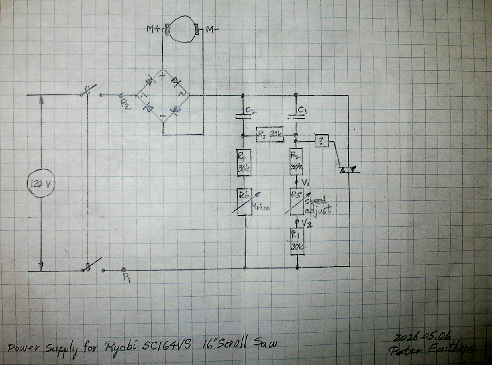
A sketch of the circuit is here. https://easthope.ca/RyobiScrollSawSC164VSboard.jpg
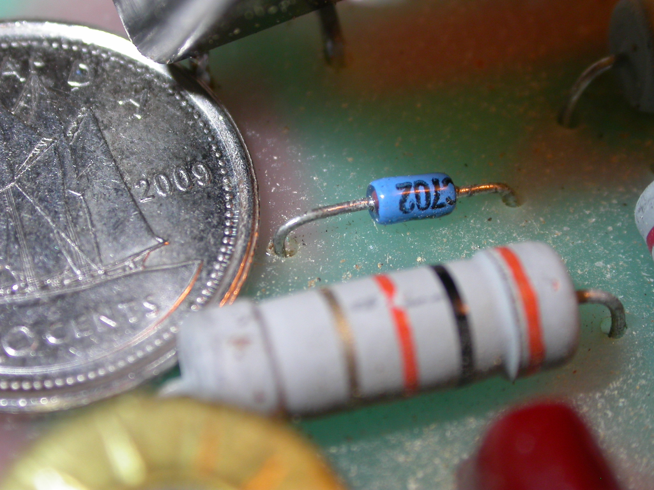
A search for "DIAC C702" gave these pages.
https://www.aliexpress.com/s/wiki-ssr/article/db3-c702-diode https://www.st.com/resource/en/datasheet/db3.pdf
In one of the documents, mention of a DIAC feeding the gate of a TRIAC
is consistent with the observed circuit.
In a week or two, can check Lee's Electronic Components here in
Vancouver for a replacment; a C702 or a DB3.
Meanwhile I'm curious about the circuit. R5 adjusts the voltage
delivered to the gate of the TRIAC. What do C2, R3, R4 and R6 add to
that?
Thanks, ... P.
They control the timing (what phase angle) of the trigger to the triac.
Maybe the simplest way to think of it is to picture 180 degrees of a
sine wave and consider how long the triac conducts if the trigger is
applied at 0 degrees, 1 degree, 2 degrees etc. When the trigger pulse "arrives" at the gate, the triac turns on and stays on as long as a
certain minimum current, called the "holding current" flows. When the
sine wave reaches 180 degrees there is no current so the triac turns
off. The sooner in the cycle the triac is triggered the longer it
conducts, providing input to the bridge and therefore power to the
motor, thus controlling its speed. There's a lot more that could be
said about triacs but that's a small overview.
Ed
--- Synchronet 3.21f-Linux NewsLink 1.2