wave is appreciated in advance. Also, what does "P2 < P1" signify on
the current probe?
wave is appreciated in advance. Also, what does "P2 < P1" signify on
the current probe?
There's a fellow on Youtube (HairyDave) who tears down a lot of COB
displays, it might be worth checking if he's had a lokk at one like
your's.
On Sun, 12 Apr 2026 10:48:05 +0100, JM
<sunaecoNoChoppedPork@gmail.com> wrote:
There's a fellow on Youtube (HairyDave) who tears down a lot of COB >>displays, it might be worth checking if he's had a lokk at one like
your's.
Sorry - should be bigclivedotcom. (Although he is hairy as well as
big...)
Recent thread topic transitioned to a tentative opinion on a work-in- >progress webpage:
<https://crcomp.net/ledfilament/index.php>
Radiography imparts interesting insight. Second opinions welcome!
The current waveform flopped. Any advice on how to use a Fluke
80i-1000s connected to a Tek 2465B to display the 120 VAC current
wave is appreciated in advance. Also, what does "P2 < P1" signify on
the current probe?
On Sun, 12 Apr 2026 10:50:18 +0100, JM
<sunaecoNoChoppedPork@gmail.com> wrote:
On Sun, 12 Apr 2026 10:48:05 +0100, JM
<sunaecoNoChoppedPork@gmail.com> wrote:
There's a fellow on Youtube (HairyDave) who tears down a lot of COB >>>displays, it might be worth checking if he's had a lokk at one like >>>your's.
Sorry - should be bigclivedotcom. (Although he is hairy as well as
big...)
https://www.youtube.com/watch?v=hFtfMtFSD8A
Somewhat similar to your devices, although twice as many LEDs.
Recent thread topic transitioned to a tentative opinion on a work-in- progress webpage:
<https://crcomp.net/ledfilament/index.php>
Radiography imparts interesting insight. Second opinions welcome!
The current waveform flopped. Any advice on how to use a Fluke
80i-1000s connected to a Tek 2465B to display the 120 VAC current
wave is appreciated in advance. Also, what does "P2 < P1" signify on
the current probe?
--
73, Don, WD7Q veritas _|_
liberabit | https://www.qsl.net/kb7rpu vos |
Don <g@crcomp.net> wrote:
Recent thread topic transitioned to a tentative opinion on a work-in-
progress webpage:
<https://crcomp.net/ledfilament/index.php>
Radiography imparts interesting insight. Second opinions welcome!
The current waveform flopped. Any advice on how to use a Fluke
80i-1000s connected to a Tek 2465B to display the 120 VAC current
wave is appreciated in advance. Also, what does "P2 < P1" signify on
the current probe?
--
73, Don, WD7Q veritas _|_
liberabit |
https://www.qsl.net/kb7rpu vos |
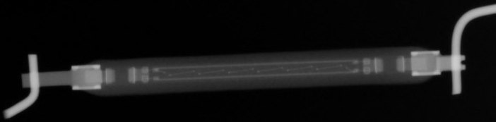
Looks like radiograph shows resistors at each end. Each resistor connects
to two wire bonded diode chips then a series string of seven led chips. So >basically seven LEDs inside a bridge rectifier with series resistors to
limit current.
On Mon, 13 Apr 2026 07:40:37 -0000 (UTC), piglet
<erichpwagner@hotmail.com> wrote:
Don <g@crcomp.net> wrote:
Recent thread topic transitioned to a tentative opinion on a work-in-
progress webpage:
<https://crcomp.net/ledfilament/index.php>
Radiography imparts interesting insight. Second opinions welcome!
The current waveform flopped. Any advice on how to use a Fluke
80i-1000s connected to a Tek 2465B to display the 120 VAC current
wave is appreciated in advance. Also, what does "P2 < P1" signify on
the current probe?
--
73, Don, WD7Q veritas _|_ >>> liberabit |
https://www.qsl.net/kb7rpu vos |
Looks like radiograph shows resistors at each end. Each resistor connects
to two wire bonded diode chips then a series string of seven led chips. So >> basically seven LEDs inside a bridge rectifier with series resistors to
limit current.
Likely no rectifier and more than seven LEDs. The current waveform
would reveal much. Or a couple of DC V-I curves.
John Larkin
Highland Tech Glen Canyon Design Center
Lunatic Fringe Electronics
The diodes are visible next the resistors even the bond wires are faintly >visible in the photo.
The diodes are visible next the resistors even the bond wires are faintly >>visible in the photo.
You are probably correct, but easy enough for Don to check by using a
DC supply to check conduction with both polarities.
JM wrote:
The diodes are visible next the resistors even the bond wires are faintly >>>visible in the photo.
You are probably correct, but easy enough for Don to check by using a
DC supply to check conduction with both polarities.
Yes. Graph and don't guess.
john larkin wrote:
JM wrote:
The diodes are visible next the resistors even the bond wires are faintly >>>>visible in the photo.
You are probably correct, but easy enough for Don to check by using a
DC supply to check conduction with both polarities.
Yes. Graph and don't guess.
OK you guys, lots of excellent ideas! The DC idea's easiest, so it's
first. Big Clive's youtube link now appears as a Footnote on the
pertinent page:
<https://crcomp.net/ledfilament/index.php>
The webpage also includes a couple of new images where 68 VDC is applied
to barely illuminate the filament's CoBs, first in one direction, and
then the opposite. How do you graph such empirical data?
Anyhow, as expected, seven filament CoBs illuminate regardless of
DC polarity. Perhaps each of the seven CoBs contains a couple of LEDs,
cross connected to conduct current through the anode of one LED, while
the cathode of its coupled LED blocks current?
JM, elsewhere you mention fourteen illuminated CoBs in Big Clive's
video. It seems significant that fourteen CoBs are also illuminated in
my filament (seven for each DC polarity).
The filament also contains a small hole on one lead to denote its
anode. But it's pointless because the filament conducts in either
direction.
Does one factory in China create CoB filaments for both AC and DC
applications? So users end up with filaments filled with fourteen CoBs
and an anode hole in one lead?
john larkin wrote:
JM wrote:
The diodes are visible next the resistors even the bond wires are faintly >>>>visible in the photo.
You are probably correct, but easy enough for Don to check by using a
DC supply to check conduction with both polarities.
Yes. Graph and don't guess.
OK you guys, lots of excellent ideas! The DC idea's easiest, so it's
first. Big Clive's youtube link now appears as a Footnote on the
pertinent page:
<https://crcomp.net/ledfilament/index.php>
The webpage also includes a couple of new images where 68 VDC is applied
to barely illuminate the filament's CoBs, first in one direction, and
then the opposite. How do you graph such empirical data?
Anyhow, as expected, seven filament CoBs illuminate regardless of
DC polarity. Perhaps each of the seven CoBs contains a couple of LEDs,
cross connected to conduct current through the anode of one LED, while
the cathode of its coupled LED blocks current?
On Tue, 14 Apr 2026 12:25:57 -0000 (UTC), "Don" <g@crcomp.net> wrote:
john larkin wrote:
JM wrote:
The diodes are visible next the resistors even the bond wires are faintly >>>>> visible in the photo.
You are probably correct, but easy enough for Don to check by using a
DC supply to check conduction with both polarities.
Yes. Graph and don't guess.
OK you guys, lots of excellent ideas! The DC idea's easiest, so it's
first. Big Clive's youtube link now appears as a Footnote on the
pertinent page:
<https://crcomp.net/ledfilament/index.php>
The webpage also includes a couple of new images where 68 VDC is applied
to barely illuminate the filament's CoBs, first in one direction, and
then the opposite. How do you graph such empirical data?
Anyhow, as expected, seven filament CoBs illuminate regardless of
DC polarity. Perhaps each of the seven CoBs contains a couple of LEDs,
cross connected to conduct current through the anode of one LED, while
the cathode of its coupled LED blocks current?
The xray sure doesn't look like there is a bridge rectifier.
https://crcomp.net/ledfilament/top.png
so I expect the LEDs are connected antiparallel.
If 68v is the turnon threshold, and a blue LED needs, say 2.8 to light
up a bit, there are roughly 24 LEDs in series.
What someone should do is graph current vs voltage, both polarities.
On 15/04/2026 1:21 am, john larkin wrote:
On Tue, 14 Apr 2026 12:25:57 -0000 (UTC), "Don" <g@crcomp.net> wrote:
john larkin wrote:
JM wrote:
The diodes are visible next the resistors even the bond wires are faintly
visible in the photo.
You are probably correct, but easy enough for Don to check by using a >>>>> DC supply to check conduction with both polarities.
Yes. Graph and don't guess.
OK you guys, lots of excellent ideas! The DC idea's easiest, so it's
first. Big Clive's youtube link now appears as a Footnote on the
pertinent page:
<https://crcomp.net/ledfilament/index.php>
The webpage also includes a couple of new images where 68 VDC is applied >>> to barely illuminate the filament's CoBs, first in one direction, and
then the opposite. How do you graph such empirical data?
Anyhow, as expected, seven filament CoBs illuminate regardless of
DC polarity. Perhaps each of the seven CoBs contains a couple of LEDs,
cross connected to conduct current through the anode of one LED, while
the cathode of its coupled LED blocks current?
The xray sure doesn't look like there is a bridge rectifier.
The four rectifiers creating the bridge rectifier may not be mounted >together as a discrete bridge rectifier, but that doesn't stop them
working together to create the same effect.
https://crcomp.net/ledfilament/top.png
so I expect the LEDs are connected antiparallel.
That would mean twice as many LEDs, which would be a much more expensive >solution.
If 68v is the turnon threshold, and a blue LED needs, say 2.8 to light
up a bit, there are roughly 24 LEDs in series.
There might be, if anybody could see them on the X-rays. Google says
that blue LED drop between 3.0V and 3.4V. Seven of the them would drop >between 21 and 24 V and enough resistance to soak up the remaining 44V
would make the current tolerably stable against self-heating in the LEDs >(whose forward voltage drops as the junction temperature increases).
https://descargas.cetronic.es/WW05A3SBQ4-N.pdf
What someone should do is graph current vs voltage, both polarities.
What John Larkin needs to do is to think a bit harder.
On Wed, 15 Apr 2026 02:48:59 +1000, Bill Sloman <bill.sloman@ieee.org>
wrote:
On 15/04/2026 1:21 am, john larkin wrote:
On Tue, 14 Apr 2026 12:25:57 -0000 (UTC), "Don" <g@crcomp.net> wrote:
john larkin wrote:
JM wrote:
The diodes are visible next the resistors even the bond wires are faintly
visible in the photo.
You are probably correct, but easy enough for Don to check by using a >>>>>> DC supply to check conduction with both polarities.
Yes. Graph and don't guess.
OK you guys, lots of excellent ideas! The DC idea's easiest, so it's
first. Big Clive's youtube link now appears as a Footnote on the
pertinent page:
<https://crcomp.net/ledfilament/index.php>
The webpage also includes a couple of new images where 68 VDC is applied >>>> to barely illuminate the filament's CoBs, first in one direction, and
then the opposite. How do you graph such empirical data?
Anyhow, as expected, seven filament CoBs illuminate regardless of >>>> DC polarity. Perhaps each of the seven CoBs contains a couple of LEDs, >>>> cross connected to conduct current through the anode of one LED, while >>>> the cathode of its coupled LED blocks current?
The xray sure doesn't look like there is a bridge rectifier.
The four rectifiers creating the bridge rectifier may not be mounted
together as a discrete bridge rectifier, but that doesn't stop them
working together to create the same effect.
https://crcomp.net/ledfilament/top.png
so I expect the LEDs are connected antiparallel.
That would mean twice as many LEDs, which would be a much more expensive
solution.
There's no obvious bridge in the xray, but resolution isn't very good.
There are ways to decap a plastic-potted IC.
If 68v is the turnon threshold, and a blue LED needs, say 2.8 to light
up a bit, there are roughly 24 LEDs in series.
There might be, if anybody could see them on the X-rays. Google says
that blue LED drop between 3.0V and 3.4V. Seven of the them would drop
between 21 and 24 V and enough resistance to soak up the remaining 44V
would make the current tolerably stable against self-heating in the LEDs
(whose forward voltage drops as the junction temperature increases).
https://descargas.cetronic.es/WW05A3SBQ4-N.pdf
Look at the V-I curve on that part. It conducts 1 mA at about 2.8
volts, and would be visible at way lower current. 1 uA might be
visible in dim room light.
What someone should do is graph current vs voltage, both polarities.
What John Larkin needs to do is to think a bit harder.
Well, I do have a day job.
John Larkin
Highland Tech Glen Canyon Design Center
Lunatic Fringe Electronics
On Tue, 14 Apr 2026 12:25:57 -0000 (UTC), "Don" <g@crcomp.net> wrote:
john larkin wrote:
JM wrote:
The diodes are visible next the resistors even the bond wires are faintly >>>>>visible in the photo.
You are probably correct, but easy enough for Don to check by using a >>>>DC supply to check conduction with both polarities.
Yes. Graph and don't guess.
OK you guys, lots of excellent ideas! The DC idea's easiest, so it's
first. Big Clive's youtube link now appears as a Footnote on the
pertinent page:
<https://crcomp.net/ledfilament/index.php>
The webpage also includes a couple of new images where 68 VDC is applied
to barely illuminate the filament's CoBs, first in one direction, and
then the opposite. How do you graph such empirical data?
Anyhow, as expected, seven filament CoBs illuminate regardless of
DC polarity. Perhaps each of the seven CoBs contains a couple of LEDs, >>cross connected to conduct current through the anode of one LED, while
the cathode of its coupled LED blocks current?
The xray sure doesn't look like there is a bridge rectifier.
https://crcomp.net/ledfilament/top.png
so I expect the LEDs are connected antiparallel.
If 68v is the turnon threshold, and a blue LED needs, say 2.8 to light
up a bit, there are roughly 24 LEDs in series.
What someone should do is graph current vs voltage, both polarities.
John Larkin
Highland Tech Glen Canyon Design Center
Lunatic Fringe Electronics
On 14/04/2026 7:14 pm, john larkin wrote:
On Wed, 15 Apr 2026 02:48:59 +1000, Bill Sloman <bill.sloman@ieee.org>
wrote:
On 15/04/2026 1:21 am, john larkin wrote:
On Tue, 14 Apr 2026 12:25:57 -0000 (UTC), "Don" <g@crcomp.net> wrote:
john larkin wrote:
JM wrote:
The diodes are visible next the resistors even the bond wires are faintly
visible in the photo.
You are probably correct, but easy enough for Don to check by using a >>>>>>> DC supply to check conduction with both polarities.
Yes. Graph and don't guess.
OK you guys, lots of excellent ideas! The DC idea's easiest, so it's >>>>> first. Big Clive's youtube link now appears as a Footnote on the
pertinent page:
<https://crcomp.net/ledfilament/index.php>
The webpage also includes a couple of new images where 68 VDC is applied >>>>> to barely illuminate the filament's CoBs, first in one direction, and >>>>> then the opposite. How do you graph such empirical data?
Anyhow, as expected, seven filament CoBs illuminate regardless of >>>>> DC polarity. Perhaps each of the seven CoBs contains a couple of LEDs, >>>>> cross connected to conduct current through the anode of one LED, while >>>>> the cathode of its coupled LED blocks current?
The xray sure doesn't look like there is a bridge rectifier.
The four rectifiers creating the bridge rectifier may not be mounted
together as a discrete bridge rectifier, but that doesn't stop them
working together to create the same effect.
https://crcomp.net/ledfilament/top.png
so I expect the LEDs are connected antiparallel.
That would mean twice as many LEDs, which would be a much more expensive >>> solution.
There's no obvious bridge in the xray, but resolution isn't very good.
There are ways to decap a plastic-potted IC.
If 68v is the turnon threshold, and a blue LED needs, say 2.8 to light >>>> up a bit, there are roughly 24 LEDs in series.
There might be, if anybody could see them on the X-rays. Google says
that blue LED drop between 3.0V and 3.4V. Seven of the them would drop
between 21 and 24 V and enough resistance to soak up the remaining 44V
would make the current tolerably stable against self-heating in the LEDs >>> (whose forward voltage drops as the junction temperature increases).
https://descargas.cetronic.es/WW05A3SBQ4-N.pdf
Look at the V-I curve on that part. It conducts 1 mA at about 2.8
volts, and would be visible at way lower current. 1 uA might be
visible in dim room light.
What someone should do is graph current vs voltage, both polarities.
What John Larkin needs to do is to think a bit harder.
Well, I do have a day job.
John Larkin
Highland Tech Glen Canyon Design Center
Lunatic Fringe Electronics
Can you see the four diodes now ...?
<https://www.dropbox.com/scl/fi/4kcz56xykw1780z3qad3w/COB_LED.pdf?rlkey=b5mz77rs8pbwzv7bt9n5sfae3&st=x8h1gsgq&raw=1>
piglet
On Tue, 14 Apr 2026 08:21:18 -0700, john larkin <jl@glen--canyon.com>
wrote:
On Tue, 14 Apr 2026 12:25:57 -0000 (UTC), "Don" <g@crcomp.net> wrote:
john larkin wrote:
JM wrote:
The diodes are visible next the resistors even the bond wires are faintly >>>>>>visible in the photo.
You are probably correct, but easy enough for Don to check by using a >>>>>DC supply to check conduction with both polarities.
Yes. Graph and don't guess.
OK you guys, lots of excellent ideas! The DC idea's easiest, so it's >>>first. Big Clive's youtube link now appears as a Footnote on the >>>pertinent page:
<https://crcomp.net/ledfilament/index.php>
The webpage also includes a couple of new images where 68 VDC is applied >>>to barely illuminate the filament's CoBs, first in one direction, and >>>then the opposite. How do you graph such empirical data?
Anyhow, as expected, seven filament CoBs illuminate regardless of
DC polarity. Perhaps each of the seven CoBs contains a couple of LEDs, >>>cross connected to conduct current through the anode of one LED, while >>>the cathode of its coupled LED blocks current?
The xray sure doesn't look like there is a bridge rectifier.
https://crcomp.net/ledfilament/top.png
so I expect the LEDs are connected antiparallel.
If 68v is the turnon threshold, and a blue LED needs, say 2.8 to light
up a bit, there are roughly 24 LEDs in series.
What someone should do is graph current vs voltage, both polarities.
John Larkin
Highland Tech Glen Canyon Design Center
Lunatic Fringe Electronics
https://mega.nz/file/h98BgYSS#xF8fYYcMfE7qY0TWBPLaC3QjEQ0eeRiZnUr_qJsqdx4
(Note that connections to a diode die are top/bottom).
All he needs to do is measure the current at a couple of dc voltages
(both enough to illuminate the LEDs) and calculate the series R from
delta V/ delta I. What else is there to know?
On Tue, 14 Apr 2026 19:42:17 +0100, JM
<sunaecoNoChoppedPork@gmail.com> wrote:
On Tue, 14 Apr 2026 08:21:18 -0700, john larkin <jl@glen--canyon.com> >>wrote:
On Tue, 14 Apr 2026 12:25:57 -0000 (UTC), "Don" <g@crcomp.net> wrote:
john larkin wrote:
JM wrote:
The diodes are visible next the resistors even the bond wires are faintly
visible in the photo.
You are probably correct, but easy enough for Don to check by using a >>>>>>DC supply to check conduction with both polarities.
Yes. Graph and don't guess.
OK you guys, lots of excellent ideas! The DC idea's easiest, so it's >>>>first. Big Clive's youtube link now appears as a Footnote on the >>>>pertinent page:
<https://crcomp.net/ledfilament/index.php>
The webpage also includes a couple of new images where 68 VDC is applied >>>>to barely illuminate the filament's CoBs, first in one direction, and >>>>then the opposite. How do you graph such empirical data?
Anyhow, as expected, seven filament CoBs illuminate regardless of >>>>DC polarity. Perhaps each of the seven CoBs contains a couple of LEDs, >>>>cross connected to conduct current through the anode of one LED, while >>>>the cathode of its coupled LED blocks current?
The xray sure doesn't look like there is a bridge rectifier.
https://crcomp.net/ledfilament/top.png
so I expect the LEDs are connected antiparallel.
If 68v is the turnon threshold, and a blue LED needs, say 2.8 to light
up a bit, there are roughly 24 LEDs in series.
What someone should do is graph current vs voltage, both polarities.
John Larkin
Highland Tech Glen Canyon Design Center
Lunatic Fringe Electronics
https://mega.nz/file/h98BgYSS#xF8fYYcMfE7qY0TWBPLaC3QjEQ0eeRiZnUr_qJsqdx4
(Note that connections to a diode die are top/bottom).
What use would diodes be in series with the assumed end resistors?
Draw a circuit please.
All he needs to do is measure the current at a couple of dc voltages
(both enough to illuminate the LEDs) and calculate the series R from
delta V/ delta I. What else is there to know?
John Larkin
Highland Tech Glen Canyon Design Center
Lunatic Fringe Electronics
On Tue, 14 Apr 2026 19:25:07 +0100, piglet <erichpwagner@hotmail.com>
wrote:
On 14/04/2026 7:14 pm, john larkin wrote:
On Wed, 15 Apr 2026 02:48:59 +1000, Bill Sloman <bill.sloman@ieee.org>
wrote:
On 15/04/2026 1:21 am, john larkin wrote:
On Tue, 14 Apr 2026 12:25:57 -0000 (UTC), "Don" <g@crcomp.net> wrote: >>>>>
john larkin wrote:
JM wrote:
The diodes are visible next the resistors even the bond wires are faintly
visible in the photo.
You are probably correct, but easy enough for Don to check by using a >>>>>>>> DC supply to check conduction with both polarities.
Yes. Graph and don't guess.
OK you guys, lots of excellent ideas! The DC idea's easiest, so it's >>>>>> first. Big Clive's youtube link now appears as a Footnote on the
pertinent page:
<https://crcomp.net/ledfilament/index.php>
The webpage also includes a couple of new images where 68 VDC is applied >>>>>> to barely illuminate the filament's CoBs, first in one direction, and >>>>>> then the opposite. How do you graph such empirical data?
Anyhow, as expected, seven filament CoBs illuminate regardless of
DC polarity. Perhaps each of the seven CoBs contains a couple of LEDs, >>>>>> cross connected to conduct current through the anode of one LED, while >>>>>> the cathode of its coupled LED blocks current?
The xray sure doesn't look like there is a bridge rectifier.
The four rectifiers creating the bridge rectifier may not be mounted
together as a discrete bridge rectifier, but that doesn't stop them
working together to create the same effect.
https://crcomp.net/ledfilament/top.png
so I expect the LEDs are connected antiparallel.
That would mean twice as many LEDs, which would be a much more expensive >>>> solution.
There's no obvious bridge in the xray, but resolution isn't very good.
There are ways to decap a plastic-potted IC.
If 68v is the turnon threshold, and a blue LED needs, say 2.8 to light >>>>> up a bit, there are roughly 24 LEDs in series.
There might be, if anybody could see them on the X-rays. Google says
that blue LED drop between 3.0V and 3.4V. Seven of the them would drop >>>> between 21 and 24 V and enough resistance to soak up the remaining 44V >>>> would make the current tolerably stable against self-heating in the LEDs >>>> (whose forward voltage drops as the junction temperature increases).
https://descargas.cetronic.es/WW05A3SBQ4-N.pdf
Look at the V-I curve on that part. It conducts 1 mA at about 2.8
volts, and would be visible at way lower current. 1 uA might be
visible in dim room light.
What someone should do is graph current vs voltage, both polarities.
What John Larkin needs to do is to think a bit harder.
Well, I do have a day job.
John Larkin
Highland Tech Glen Canyon Design Center
Lunatic Fringe Electronics
Can you see the four diodes now ...?
<https://www.dropbox.com/scl/fi/4kcz56xykw1780z3qad3w/COB_LED.pdf?rlkey=b5mz77rs8pbwzv7bt9n5sfae3&st=x8h1gsgq&raw=1>
piglet
You beat me to it.
On Tue, 14 Apr 2026 19:42:17 +0100, JM
<sunaecoNoChoppedPork@gmail.com> wrote:
On Tue, 14 Apr 2026 08:21:18 -0700, john larkin <jl@glen--canyon.com>
wrote:
On Tue, 14 Apr 2026 12:25:57 -0000 (UTC), "Don" <g@crcomp.net> wrote:
john larkin wrote:
JM wrote:
The diodes are visible next the resistors even the bond wires are faintly
visible in the photo.
You are probably correct, but easy enough for Don to check by using a >>>>>> DC supply to check conduction with both polarities.
Yes. Graph and don't guess.
OK you guys, lots of excellent ideas! The DC idea's easiest, so it's
first. Big Clive's youtube link now appears as a Footnote on the
pertinent page:
<https://crcomp.net/ledfilament/index.php>
The webpage also includes a couple of new images where 68 VDC is applied >>>> to barely illuminate the filament's CoBs, first in one direction, and
then the opposite. How do you graph such empirical data?
Anyhow, as expected, seven filament CoBs illuminate regardless of
DC polarity. Perhaps each of the seven CoBs contains a couple of LEDs, >>>> cross connected to conduct current through the anode of one LED, while >>>> the cathode of its coupled LED blocks current?
The xray sure doesn't look like there is a bridge rectifier.
https://crcomp.net/ledfilament/top.png
so I expect the LEDs are connected antiparallel.
If 68v is the turnon threshold, and a blue LED needs, say 2.8 to light
up a bit, there are roughly 24 LEDs in series.
What someone should do is graph current vs voltage, both polarities.
John Larkin
Highland Tech Glen Canyon Design Center
Lunatic Fringe Electronics
https://mega.nz/file/h98BgYSS#xF8fYYcMfE7qY0TWBPLaC3QjEQ0eeRiZnUr_qJsqdx4
(Note that connections to a diode die are top/bottom).
What use would diodes be in series with the assumed end resistors?
Draw a circuit please.
All he needs to do is measure the current at a couple of dc voltages
(both enough to illuminate the LEDs) and calculate the series R from
delta V/ delta I. What else is there to know?
John Larkin
Highland Tech Glen Canyon Design Center
Lunatic Fringe Electronics
On 14/04/2026 8:57 pm, john larkin wrote:
On Tue, 14 Apr 2026 19:42:17 +0100, JM
<sunaecoNoChoppedPork@gmail.com> wrote:
On Tue, 14 Apr 2026 08:21:18 -0700, john larkin <jl@glen--canyon.com>
wrote:
On Tue, 14 Apr 2026 12:25:57 -0000 (UTC), "Don" <g@crcomp.net> wrote:
john larkin wrote:
JM wrote:
The diodes are visible next the resistors even the bond wires are faintly
visible in the photo.
You are probably correct, but easy enough for Don to check by using a >>>>>>> DC supply to check conduction with both polarities.
Yes. Graph and don't guess.
OK you guys, lots of excellent ideas! The DC idea's easiest, so it's >>>>> first. Big Clive's youtube link now appears as a Footnote on the
pertinent page:
<https://crcomp.net/ledfilament/index.php>
The webpage also includes a couple of new images where 68 VDC is applied >>>>> to barely illuminate the filament's CoBs, first in one direction, and >>>>> then the opposite. How do you graph such empirical data?
Anyhow, as expected, seven filament CoBs illuminate regardless of >>>>> DC polarity. Perhaps each of the seven CoBs contains a couple of LEDs, >>>>> cross connected to conduct current through the anode of one LED, while >>>>> the cathode of its coupled LED blocks current?
The xray sure doesn't look like there is a bridge rectifier.
https://crcomp.net/ledfilament/top.png
so I expect the LEDs are connected antiparallel.
If 68v is the turnon threshold, and a blue LED needs, say 2.8 to light >>>> up a bit, there are roughly 24 LEDs in series.
What someone should do is graph current vs voltage, both polarities.
John Larkin
Highland Tech Glen Canyon Design Center
Lunatic Fringe Electronics
https://mega.nz/file/h98BgYSS#xF8fYYcMfE7qY0TWBPLaC3QjEQ0eeRiZnUr_qJsqdx4 >>>
(Note that connections to a diode die are top/bottom).
What use would diodes be in series with the assumed end resistors?
Draw a circuit please.
All he needs to do is measure the current at a couple of dc voltages
(both enough to illuminate the LEDs) and calculate the series R from
delta V/ delta I. What else is there to know?
John Larkin
Highland Tech Glen Canyon Design Center
Lunatic Fringe Electronics
You ask, you get ...
<https://www.dropbox.com/scl/fi/racdrahimk5nexxdjrm4u/COB_LED_SCH.pdf?rlkey=pdgijpu70o636nk2dz83x78jy&st=1s9g3bd2&raw=1>
piglet
On 14/04/2026 8:57 pm, john larkin wrote:
On Tue, 14 Apr 2026 19:42:17 +0100, JM <sunaecoNoChoppedPork@gmail.com> wrote:
On Tue, 14 Apr 2026 08:21:18 -0700, john larkin <jl@glen--canyon.com> wrote:
On Tue, 14 Apr 2026 12:25:57 -0000 (UTC), "Don" <g@crcomp.net> wrote: >>>>> john larkin wrote:
JM wrote:
The diodes are visible next the resistors even the bond wires are faintly
visible in the photo.
You are probably correct, but easy enough for Don to check by using a >>>>>>> DC supply to check conduction with both polarities.
Yes. Graph and don't guess.
OK you guys, lots of excellent ideas! The DC idea's easiest, so it's >>>>> first. Big Clive's youtube link now appears as a Footnote on the
pertinent page:
<https://crcomp.net/ledfilament/index.php>
The webpage also includes a couple of new images where 68 VDC is applied >>>>> to barely illuminate the filament's CoBs, first in one direction, and >>>>> then the opposite. How do you graph such empirical data?
Anyhow, as expected, seven filament CoBs illuminate regardless of >>>>> DC polarity. Perhaps each of the seven CoBs contains a couple of LEDs, >>>>> cross connected to conduct current through the anode of one LED, while >>>>> the cathode of its coupled LED blocks current?
The xray sure doesn't look like there is a bridge rectifier.
https://crcomp.net/ledfilament/top.png
If 68v is the turnon threshold, and a blue LED needs, say 2.8 to light >>>> up a bit, there are roughly 24 LEDs in series.
What someone should do is graph current vs voltage, both polarities.
https://mega.nz/file/h98BgYSS#xF8fYYcMfE7qY0TWBPLaC3QjEQ0eeRiZnUr_qJsqdx4 >>>
(Note that connections to a diode die are top/bottom).
What use would diodes be in series with the assumed end resistors?
Draw a circuit please.
All he needs to do is measure the current at a couple of dc voltages
(both enough to illuminate the LEDs) and calculate the series R from
delta V/ delta I. What else is there to know?
You ask, you get ...
<https://www.dropbox.com/scl/fi/racdrahimk5nexxdjrm4u/COB_LED_SCH.pdf?rlkey=pdgijpu70o636nk2dz83x78jy&st=1s9g3bd2&raw=1>
piglet <erichpwagner@hotmail.com> wrote:
On 14/04/2026 8:57 pm, john larkin wrote:
On Tue, 14 Apr 2026 19:42:17 +0100, JM <sunaecoNoChoppedPork@gmail.com> wrote:
On Tue, 14 Apr 2026 08:21:18 -0700, john larkin <jl@glen--canyon.com> wrote:
On Tue, 14 Apr 2026 12:25:57 -0000 (UTC), "Don" <g@crcomp.net> wrote: >>>>>> john larkin wrote:
JM wrote:
The diodes are visible next the resistors even the bond wires are faintly
visible in the photo.
You are probably correct, but easy enough for Don to check by using a >>>>>>>> DC supply to check conduction with both polarities.
Yes. Graph and don't guess.
OK you guys, lots of excellent ideas! The DC idea's easiest, so it's >>>>>> first. Big Clive's youtube link now appears as a Footnote on the
pertinent page:
<https://crcomp.net/ledfilament/index.php>
The webpage also includes a couple of new images where 68 VDC is applied >>>>>> to barely illuminate the filament's CoBs, first in one direction, and >>>>>> then the opposite. How do you graph such empirical data?
Anyhow, as expected, seven filament CoBs illuminate regardless of
DC polarity. Perhaps each of the seven CoBs contains a couple of LEDs, >>>>>> cross connected to conduct current through the anode of one LED, while >>>>>> the cathode of its coupled LED blocks current?
The xray sure doesn't look like there is a bridge rectifier.
https://crcomp.net/ledfilament/top.png
If 68v is the turnon threshold, and a blue LED needs, say 2.8 to light >>>>> up a bit, there are roughly 24 LEDs in series.
What someone should do is graph current vs voltage, both polarities.
https://mega.nz/file/h98BgYSS#xF8fYYcMfE7qY0TWBPLaC3QjEQ0eeRiZnUr_qJsqdx4 >>>>
(Note that connections to a diode die are top/bottom).
What use would diodes be in series with the assumed end resistors?
Draw a circuit please.
All he needs to do is measure the current at a couple of dc voltages
(both enough to illuminate the LEDs) and calculate the series R from
delta V/ delta I. What else is there to know?
You ask, you get ...
<https://www.dropbox.com/scl/fi/racdrahimk5nexxdjrm4u/COB_LED_SCH.pdf?rlkey=pdgijpu70o636nk2dz83x78jy&st=1s9g3bd2&raw=1>
Congratulations, you did it again!
Your adroit analysis is anticlimactic. Because it eliminates my expectations of exotic electronic elements such as miniaturized
MOSFETs.
Yet, in retrospect, it's simple to see how power elements demand a relatively large footprint in order to handle a high voltage. It's only simple now because you saw it first.
Anyhow, your radiographic interpretation eloquently puts everything
into perspective. Is it possible for you to give me permission to include
it on the webpage with a credit to you?
You also confirm my suspicion of a half-wave rectifier at each end.
One half-wave connected to Line and another attached to Neutral. This
gives me enough insight to include an illustrative kicad schematic on
the page.
Then the only things left to do are a detailed write-up and a pesky
V-I curve. Even if the curve only shows a resistive load it still gives
me an excuse to teach myself how to handle a Fluke current probe.
--
73, Don, WD7Q veritas _|_
liberabit | https://www.qsl.net/wd7q vos |
| Sysop: | Amessyroom |
|---|---|
| Location: | Fayetteville, NC |
| Users: | 63 |
| Nodes: | 6 (0 / 6) |
| Uptime: | 493001:39:36 |
| Calls: | 840 |
| Files: | 1,302 |
| D/L today: |
9 files (7,185K bytes) |
| Messages: | 267,829 |