As discussed in a previous thread, I've placed an order for a pair of
new 6146s for the K.W.Viceroy. I find that the alignment instructions
which are available for the Mk III also apply, in part, to my Mk II.
The SSB generator is identical.
The SSB generator consists of a crystal oscillator, a diode mixer and a three-crystal filter to remove the carrier and the unwanted sideband.
The oscillator crystal generates 450,000 c/s in parallel-resonant mode,
the carrier rejection crystal should reject 450,000 c/s in the series resonant mode - so those two crystals are not interchangeable even
though they are marked with the same frequency. To distinguish them,
the oscillator crystal is additionally marked "Cap 30pf" and the
rejection crystal is marked "S/R".
The instructions are to tune the oscillator by a small 'beehive' trimmer
so that it falls ito the notch of the rejector, so it would appear that
the actual oscillator frequency is not terribly critical. In practice I found that the oscillator could be adjusted a few tens of cycles either
side of 450,000 c/s but did not seem to fall into the notch.
I have now tested the rejector with a signal; generator and found that
the crystal series-notches at 433,267 c/s and has its parallel resonance
at 450,000 c/s, so it is identical with the oscillator crystal and
marked incorrectly.
These crystals are mounted in glass B7G enclosures, like valves, and
have not been manufactured for a long time, so I am unlikely to obtain
the correct notch crystal. Presumably I could 'pull' the oscillator
crystal onto the notch frequency with a lot of extra capacitance but is
there a more elegant solution (that does not involve semiconductors).?
As discussed in a previous thread, I've placed an order for a pair of
new 6146s for the K.W.Viceroy. I find that the alignment instructions
which are available for the Mk III also apply, in part, to my Mk II.
The SSB generator is identical.
The SSB generator consists of a crystal oscillator, a diode mixer and a >three-crystal filter to remove the carrier and the unwanted sideband.
The oscillator crystal generates 450,000 c/s in parallel-resonant mode,
the carrier rejection crystal should reject 450,000 c/s in the series >resonant mode - so those two crystals are not interchangeable even
though they are marked with the same frequency. To distinguish them,
the oscillator crystal is additionally marked "Cap 30pf" and the
rejection crystal is marked "S/R".
The instructions are to tune the oscillator by a small 'beehive' trimmer
so that it falls ito the notch of the rejector, so it would appear that
the actual oscillator frequency is not terribly critical. In practice I >found that the oscillator could be adjusted a few tens of cycles either
side of 450,000 c/s but did not seem to fall into the notch.
I have now tested the rejector with a signal; generator and found that
the crystal series-notches at 433,267 c/s and has its parallel resonance
at 450,000 c/s, so it is identical with the oscillator crystal and
marked incorrectly.
These crystals are mounted in glass B7G enclosures, like valves, and
have not been manufactured for a long time, so I am unlikely to obtain
the correct notch crystal. Presumably I could 'pull' the oscillator
crystal onto the notch frequency with a lot of extra capacitance but is
there a more elegant solution (that does not involve semiconductors).?
On 11/11/2026 10:03 AM, Liz Tuddenham wrote:
As discussed in a previous thread, I've placed an order for a pair of
new 6146s for the K.W.Viceroy.-a I find that the alignment instructions
which are available for the Mk III also apply, in part, to my Mk II.
The SSB generator is identical.
The SSB generator consists of a crystal oscillator, a diode mixer and a
three-crystal filter to remove the carrier and the unwanted sideband.
The oscillator crystal generates 450,000 c/s in parallel-resonant mode,
the carrier rejection crystal should reject 450,000 c/s in the series
resonant mode - so those two crystals are not interchangeable even
though they are marked with the same frequency.-a To distinguish them,
the oscillator crystal is additionally marked "Cap 30pf" and the
rejection crystal is marked "S/R".
The instructions are to tune the oscillator by a small 'beehive' trimmer
so that it falls ito the notch of the rejector, so it would appear that
the actual oscillator frequency is not terribly critical.-a In practice I
found that the oscillator could be adjusted a few tens of cycles either
side of 450,000 c/s but did not seem to fall into the notch.
I have now tested the rejector with a signal; generator and found that
the crystal series-notches at 433,267 c/s and has its parallel resonance
at 450,000 c/s, so it is identical with the oscillator crystal and
marked incorrectly.
These crystals are mounted in glass B7G enclosures, like valves, and
have not been manufactured for a long time, so I am unlikely to obtain
the correct notch crystal.-a Presumably I could 'pull' the oscillator
crystal onto the notch frequency with a lot of extra capacitance but is
there a more elegant solution (that does not involve semiconductors).?
I think ~ 20 kHz is likely too much to pull a crystal
Maybe you can replace it with a 455 kHz ceramic resonator
pulled to 450?
Ed
As discussed in a previous thread, I've placed an order for a pair of
new 6146s for the K.W.Viceroy. I find that the alignment instructions
which are available for the Mk III also apply, in part, to my Mk II.
The SSB generator is identical.
The SSB generator consists of a crystal oscillator, a diode mixer and a >three-crystal filter to remove the carrier and the unwanted sideband.
The oscillator crystal generates 450,000 c/s in parallel-resonant mode,
the carrier rejection crystal should reject 450,000 c/s in the series >resonant mode - so those two crystals are not interchangeable even
though they are marked with the same frequency. To distinguish them,
the oscillator crystal is additionally marked "Cap 30pf" and the
rejection crystal is marked "S/R".
The instructions are to tune the oscillator by a small 'beehive' trimmer
so that it falls ito the notch of the rejector, so it would appear that
the actual oscillator frequency is not terribly critical. In practice I >found that the oscillator could be adjusted a few tens of cycles either
side of 450,000 c/s but did not seem to fall into the notch.
I have now tested the rejector with a signal; generator and found that
the crystal series-notches at 433,267 c/s and has its parallel resonance
at 450,000 c/s, so it is identical with the oscillator crystal and
marked incorrectly.
These crystals are mounted in glass B7G enclosures, like valves, and
have not been manufactured for a long time, so I am unlikely to obtain
the correct notch crystal. Presumably I could 'pull' the oscillator
crystal onto the notch frequency with a lot of extra capacitance but is
there a more elegant solution (that does not involve semiconductors).?
On Wed, 11 Nov 2026 15:03:47 +0000, liz@poppyrecords.invalid.invalid
(Liz Tuddenham) wrote:
As discussed in a previous thread, I've placed an order for a pair of
new 6146s for the K.W.Viceroy. I find that the alignment instructions
which are available for the Mk III also apply, in part, to my Mk II.
The SSB generator is identical.
The SSB generator consists of a crystal oscillator, a diode mixer and a
three-crystal filter to remove the carrier and the unwanted sideband.
The oscillator crystal generates 450,000 c/s in parallel-resonant mode,
the carrier rejection crystal should reject 450,000 c/s in the series
resonant mode - so those two crystals are not interchangeable even
though they are marked with the same frequency. To distinguish them,
the oscillator crystal is additionally marked "Cap 30pf" and the
rejection crystal is marked "S/R".
The instructions are to tune the oscillator by a small 'beehive' trimmer
so that it falls ito the notch of the rejector, so it would appear that
the actual oscillator frequency is not terribly critical. In practice I
found that the oscillator could be adjusted a few tens of cycles either
side of 450,000 c/s but did not seem to fall into the notch.
I have now tested the rejector with a signal; generator and found that
the crystal series-notches at 433,267 c/s and has its parallel resonance
at 450,000 c/s, so it is identical with the oscillator crystal and
marked incorrectly.
These crystals are mounted in glass B7G enclosures, like valves, and
have not been manufactured for a long time, so I am unlikely to obtain
the correct notch crystal. Presumably I could 'pull' the oscillator
crystal onto the notch frequency with a lot of extra capacitance but is
there a more elegant solution (that does not involve semiconductors).?
I expect that a cheap FPGA and a dinky litle DAC could generate SSB.
Or even a 75-cent ARM, with its ADC for analog input, driving a
parallel DAC for output. Figure a square inch of PCB. That might be a
cool product.
John Larkin
Highland Tech Glen Canyon Design Center
Lunatic Fringe Electronics
On 11/11/26 21:57, john larkin wrote:
On Wed, 11 Nov 2026 15:03:47 +0000, liz@poppyrecords.invalid.invalid
(Liz Tuddenham) wrote:
As discussed in a previous thread, I've placed an order for a pair of
new 6146s for the K.W.Viceroy. I find that the alignment instructions
which are available for the Mk III also apply, in part, to my Mk II.
The SSB generator is identical.
The SSB generator consists of a crystal oscillator, a diode mixer and a
three-crystal filter to remove the carrier and the unwanted sideband.
The oscillator crystal generates 450,000 c/s in parallel-resonant mode,
the carrier rejection crystal should reject 450,000 c/s in the series
resonant mode - so those two crystals are not interchangeable even
though they are marked with the same frequency. To distinguish them,
the oscillator crystal is additionally marked "Cap 30pf" and the
rejection crystal is marked "S/R".
The instructions are to tune the oscillator by a small 'beehive' trimmer >>> so that it falls ito the notch of the rejector, so it would appear that
the actual oscillator frequency is not terribly critical. In practice I >>> found that the oscillator could be adjusted a few tens of cycles either
side of 450,000 c/s but did not seem to fall into the notch.
I have now tested the rejector with a signal; generator and found that
the crystal series-notches at 433,267 c/s and has its parallel resonance >>> at 450,000 c/s, so it is identical with the oscillator crystal and
marked incorrectly.
These crystals are mounted in glass B7G enclosures, like valves, and
have not been manufactured for a long time, so I am unlikely to obtain
the correct notch crystal. Presumably I could 'pull' the oscillator
crystal onto the notch frequency with a lot of extra capacitance but is
there a more elegant solution (that does not involve semiconductors).?
I expect that a cheap FPGA and a dinky litle DAC could generate SSB.
Or even a 75-cent ARM, with its ADC for analog input, driving a
parallel DAC for output. Figure a square inch of PCB. That might be a
cool product.
John Larkin
Highland Tech Glen Canyon Design Center
Lunatic Fringe Electronics
It wouldn't be a restoration then, would it?
Jeroen Belleman
On Wed, 11 Nov 2026 22:41:11 +0100, Jeroen Belleman
<jeroen@nospam.please> wrote:
On 11/11/26 21:57, john larkin wrote:
On Wed, 11 Nov 2026 15:03:47 +0000, liz@poppyrecords.invalid.invalid
(Liz Tuddenham) wrote:
As discussed in a previous thread, I've placed an order for a pair of
new 6146s for the K.W.Viceroy. I find that the alignment instructions >>> which are available for the Mk III also apply, in part, to my Mk II.
The SSB generator is identical.
The SSB generator consists of a crystal oscillator, a diode mixer and a >>> three-crystal filter to remove the carrier and the unwanted sideband.
The oscillator crystal generates 450,000 c/s in parallel-resonant mode, >>> the carrier rejection crystal should reject 450,000 c/s in the series
resonant mode - so those two crystals are not interchangeable even
though they are marked with the same frequency. To distinguish them,
the oscillator crystal is additionally marked "Cap 30pf" and the
rejection crystal is marked "S/R".
The instructions are to tune the oscillator by a small 'beehive' trimmer >>> so that it falls ito the notch of the rejector, so it would appear that >>> the actual oscillator frequency is not terribly critical. In practice I >>> found that the oscillator could be adjusted a few tens of cycles either >>> side of 450,000 c/s but did not seem to fall into the notch.
I have now tested the rejector with a signal; generator and found that >>> the crystal series-notches at 433,267 c/s and has its parallel resonance >>> at 450,000 c/s, so it is identical with the oscillator crystal and
marked incorrectly.
These crystals are mounted in glass B7G enclosures, like valves, and
have not been manufactured for a long time, so I am unlikely to obtain >>> the correct notch crystal. Presumably I could 'pull' the oscillator
crystal onto the notch frequency with a lot of extra capacitance but is >>> there a more elegant solution (that does not involve semiconductors).?
I expect that a cheap FPGA and a dinky litle DAC could generate SSB.
Or even a 75-cent ARM, with its ADC for analog input, driving a
parallel DAC for output. Figure a square inch of PCB. That might be a
cool product.
John Larkin
Highland Tech Glen Canyon Design Center
Lunatic Fringe Electronics
It wouldn't be a restoration then, would it?
Jeroen Belleman
Hide it where nobody will see it.
But it would be an interesting problem, making an SSB generator in
software.
On 11/11/2026 10:03 AM, Liz Tuddenham wrote:
As discussed in a previous thread, I've placed an order for a pair of
new 6146s for the K.W.Viceroy. I find that the alignment instructions which are available for the Mk III also apply, in part, to my Mk II.
The SSB generator is identical.
The SSB generator consists of a crystal oscillator, a diode mixer and a three-crystal filter to remove the carrier and the unwanted sideband.
The oscillator crystal generates 450,000 c/s in parallel-resonant mode,
the carrier rejection crystal should reject 450,000 c/s in the series resonant mode - so those two crystals are not interchangeable even
though they are marked with the same frequency. To distinguish them,
the oscillator crystal is additionally marked "Cap 30pf" and the
rejection crystal is marked "S/R".
The instructions are to tune the oscillator by a small 'beehive' trimmer
so that it falls ito the notch of the rejector, so it would appear that
the actual oscillator frequency is not terribly critical. In practice I found that the oscillator could be adjusted a few tens of cycles either side of 450,000 c/s but did not seem to fall into the notch.
I have now tested the rejector with a signal; generator and found that
the crystal series-notches at 433,267 c/s and has its parallel resonance
at 450,000 c/s, so it is identical with the oscillator crystal and
marked incorrectly.
These crystals are mounted in glass B7G enclosures, like valves, and
have not been manufactured for a long time, so I am unlikely to obtain
the correct notch crystal. Presumably I could 'pull' the oscillator crystal onto the notch frequency with a lot of extra capacitance but is there a more elegant solution (that does not involve semiconductors).?
I think ~ 20 kHz is likely too much to pull a crystal
Maybe you can replace it with a 455 kHz ceramic resonator
pulled to 450?
On 11/11/2026 17:21, ehsjr wrote:
On 11/11/2026 10:03 AM, Liz Tuddenham wrote:
As discussed in a previous thread, I've placed an order for a pair of
new 6146s for the K.W.Viceroy.-a I find that the alignment instructions
which are available for the Mk III also apply, in part, to my Mk II.
The SSB generator is identical.
The SSB generator consists of a crystal oscillator, a diode mixer and a
three-crystal filter to remove the carrier and the unwanted sideband.
The oscillator crystal generates 450,000 c/s in parallel-resonant mode,
the carrier rejection crystal should reject 450,000 c/s in the series
resonant mode - so those two crystals are not interchangeable even
though they are marked with the same frequency.-a To distinguish them,
the oscillator crystal is additionally marked "Cap 30pf" and the
rejection crystal is marked "S/R".
The instructions are to tune the oscillator by a small 'beehive' trimmer >> so that it falls ito the notch of the rejector, so it would appear that
the actual oscillator frequency is not terribly critical.-a In practice I >> found that the oscillator could be adjusted a few tens of cycles either
side of 450,000 c/s but did not seem to fall into the notch.
I have now tested the rejector with a signal; generator and found that
the crystal series-notches at 433,267 c/s and has its parallel resonance >> at 450,000 c/s, so it is identical with the oscillator crystal and
marked incorrectly.
These crystals are mounted in glass B7G enclosures, like valves, and
have not been manufactured for a long time, so I am unlikely to obtain
the correct notch crystal.-a Presumably I could 'pull' the oscillator
crystal onto the notch frequency with a lot of extra capacitance but is
there a more elegant solution (that does not involve semiconductors).?
I think ~ 20 kHz is likely too much to pull a crystal
Maybe you can replace it with a 455 kHz ceramic resonator
pulled to 450?
Ed
If lowering the frequency of one of the crystals would solve
the problem you could open the top of the glass envelope and
fill it with copper sulfate (sulphate) solution and
electroplate copper onto the gold electrodes on the crystal.
The extra mass should be affective at lowering the frequency
buy a useful amount. A lot of trial end error would be needed
to get it right.
If you happen to have some gold potassium cyanide lying around
then you could of course plate gold on instead of copper.
On Wed, 11 Nov 2026 15:03:47 +0000, liz@poppyrecords.invalid.invalid
(Liz Tuddenham) wrote:
As discussed in a previous thread, I've placed an order for a pair of
new 6146s for the K.W.Viceroy. I find that the alignment instructions >which are available for the Mk III also apply, in part, to my Mk II.
The SSB generator is identical.
The SSB generator consists of a crystal oscillator, a diode mixer and a >three-crystal filter to remove the carrier and the unwanted sideband.
The oscillator crystal generates 450,000 c/s in parallel-resonant mode,
the carrier rejection crystal should reject 450,000 c/s in the series >resonant mode - so those two crystals are not interchangeable even
though they are marked with the same frequency. To distinguish them,
the oscillator crystal is additionally marked "Cap 30pf" and the
rejection crystal is marked "S/R".
The instructions are to tune the oscillator by a small 'beehive' trimmer
so that it falls ito the notch of the rejector, so it would appear that
the actual oscillator frequency is not terribly critical. In practice I >found that the oscillator could be adjusted a few tens of cycles either >side of 450,000 c/s but did not seem to fall into the notch.
I have now tested the rejector with a signal; generator and found that
the crystal series-notches at 433,267 c/s and has its parallel resonance
at 450,000 c/s, so it is identical with the oscillator crystal and
marked incorrectly.
These crystals are mounted in glass B7G enclosures, like valves, and
have not been manufactured for a long time, so I am unlikely to obtain
the correct notch crystal. Presumably I could 'pull' the oscillator >crystal onto the notch frequency with a lot of extra capacitance but is >there a more elegant solution (that does not involve semiconductors).?
I suppose there is some merit in building your own test equipment. For a
low distortion and harmonic free two tone test signal on about 450 KHz, I suggest two low distortion RF signal generators, such as an old HP8640B,
and a resistive combiner/divider. Basically a shielded box, 3 BNC
connectors and 3 resistors in a "star". For 50 ohm systems, the 3
resistors are 16.7 ohms. See section on "resistive dividers" at: <https://www.digikey.com/en/articles/the-fundamentals-of-rf-power-dividers -and-combiners> Using 2 signal generators has the advantage of being able
to use any frequency within the range of the generators and to use the
same derangement for receiver IMD (3rd order intermodulation distortion) testing.
<https://en.wikipedia.org/wiki/Two-tone_testing>
The problem with this method is that old HP8640B generators cost about
$500 plus shipping.
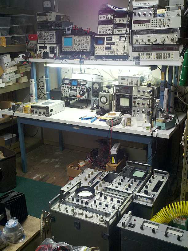
This photo is probably the last time my workbench was clean (about
2012):
<http://802.11junk.com/jeffl/pics/home/test-equip-mess.jpg>
My 2nd HP840B is hidden somewhere nearby because adding it to the pile
in the upper right might cause the shelf to collapse.
Is this a BG7 crystal?
<https://www.ebay.com/itm/305073735241> <https://www.ebay.com/itm/257627014133>
I couldn't find much on a "beehive" trimmer: <https://www.ebay.com/itm/254964971908>
I guess it's a tubular piston capacitor. See sellers description for
some details and hints.
As discussed in a previous thread, I've placed an order for a pair of
new 6146s for the K.W.Viceroy. I find that the alignment instructions
which are available for the Mk III also apply, in part, to my Mk II.
The SSB generator is identical.
The SSB generator consists of a crystal oscillator, a diode mixer and a >three-crystal filter to remove the carrier and the unwanted sideband.
The oscillator crystal generates 450,000 c/s in parallel-resonant mode,
the carrier rejection crystal should reject 450,000 c/s in the series >resonant mode - so those two crystals are not interchangeable even
though they are marked with the same frequency. To distinguish them,
the oscillator crystal is additionally marked "Cap 30pf" and the
rejection crystal is marked "S/R".
The instructions are to tune the oscillator by a small 'beehive' trimmer
so that it falls ito the notch of the rejector, so it would appear that
the actual oscillator frequency is not terribly critical. In practice I >found that the oscillator could be adjusted a few tens of cycles either
side of 450,000 c/s but did not seem to fall into the notch.
I have now tested the rejector with a signal; generator and found that
the crystal series-notches at 433,267 c/s and has its parallel resonance
at 450,000 c/s, so it is identical with the oscillator crystal and
marked incorrectly.
As discussed in a previous thread, I've placed an order for a pair of
new 6146s for the K.W.Viceroy. I find that the alignment instructions
which are available for the Mk III also apply, in part, to my Mk II.
The SSB generator is identical.
The SSB generator consists of a crystal oscillator, a diode mixer and a >three-crystal filter to remove the carrier and the unwanted sideband.
The oscillator crystal generates 450,000 c/s in parallel-resonant mode,
the carrier rejection crystal should reject 450,000 c/s in the series >resonant mode - so those two crystals are not interchangeable even
though they are marked with the same frequency. To distinguish them,
the oscillator crystal is additionally marked "Cap 30pf" and the
rejection crystal is marked "S/R".
The instructions are to tune the oscillator by a small 'beehive' trimmer
so that it falls ito the notch of the rejector, so it would appear that
the actual oscillator frequency is not terribly critical. In practice I >found that the oscillator could be adjusted a few tens of cycles either
side of 450,000 c/s but did not seem to fall into the notch.
I have now tested the rejector with a signal; generator and found that
the crystal series-notches at 433,267 c/s and has its parallel resonance
at 450,000 c/s, so it is identical with the oscillator crystal and
marked incorrectly.
john larkin <jl@glen--canyon.com> wrote:
On Wed, 11 Nov 2026 22:41:11 +0100, Jeroen Belleman
<jeroen@nospam.please> wrote:
On 11/11/26 21:57, john larkin wrote:
On Wed, 11 Nov 2026 15:03:47 +0000, liz@poppyrecords.invalid.invalid
(Liz Tuddenham) wrote:
As discussed in a previous thread, I've placed an order for a pair ofI expect that a cheap FPGA and a dinky litle DAC could generate SSB.
new 6146s for the K.W.Viceroy. I find that the alignment instructions >> >>> which are available for the Mk III also apply, in part, to my Mk II.
The SSB generator is identical.
The SSB generator consists of a crystal oscillator, a diode mixer and a >> >>> three-crystal filter to remove the carrier and the unwanted sideband.
The oscillator crystal generates 450,000 c/s in parallel-resonant mode, >> >>> the carrier rejection crystal should reject 450,000 c/s in the series
resonant mode - so those two crystals are not interchangeable even
though they are marked with the same frequency. To distinguish them,
the oscillator crystal is additionally marked "Cap 30pf" and the
rejection crystal is marked "S/R".
The instructions are to tune the oscillator by a small 'beehive' trimmer >> >>> so that it falls ito the notch of the rejector, so it would appear that >> >>> the actual oscillator frequency is not terribly critical. In practice I >> >>> found that the oscillator could be adjusted a few tens of cycles either >> >>> side of 450,000 c/s but did not seem to fall into the notch.
I have now tested the rejector with a signal; generator and found that >> >>> the crystal series-notches at 433,267 c/s and has its parallel resonance >> >>> at 450,000 c/s, so it is identical with the oscillator crystal and
marked incorrectly.
These crystals are mounted in glass B7G enclosures, like valves, and
have not been manufactured for a long time, so I am unlikely to obtain >> >>> the correct notch crystal. Presumably I could 'pull' the oscillator
crystal onto the notch frequency with a lot of extra capacitance but is >> >>> there a more elegant solution (that does not involve semiconductors).? >> >>
Or even a 75-cent ARM, with its ADC for analog input, driving a
parallel DAC for output. Figure a square inch of PCB. That might be a
cool product.
John Larkin
Highland Tech Glen Canyon Design Center
Lunatic Fringe Electronics
It wouldn't be a restoration then, would it?
Jeroen Belleman
Hide it where nobody will see it.
But it would be an interesting problem, making an SSB generator in
software.
I believe many of the current amateur transceivers do it that way using
the Weaver method.;
On Wed, 11 Nov 2026 15:03:47 +0000, liz@poppyrecords.invalid.invalid
(Liz Tuddenham) wrote:
As discussed in a previous thread, I've placed an order for a pair of. . so you measured the oscillator crystal under the same conditions,
new 6146s for the K.W.Viceroy. I find that the alignment instructions >>which are available for the Mk III also apply, in part, to my Mk II.
The SSB generator is identical.
The SSB generator consists of a crystal oscillator, a diode mixer and a >>three-crystal filter to remove the carrier and the unwanted sideband.
The oscillator crystal generates 450,000 c/s in parallel-resonant mode,
the carrier rejection crystal should reject 450,000 c/s in the series >>resonant mode - so those two crystals are not interchangeable even
though they are marked with the same frequency. To distinguish them,
the oscillator crystal is additionally marked "Cap 30pf" and the
rejection crystal is marked "S/R".
The instructions are to tune the oscillator by a small 'beehive' trimmer
so that it falls ito the notch of the rejector, so it would appear that
the actual oscillator frequency is not terribly critical. In practice I >>found that the oscillator could be adjusted a few tens of cycles either >>side of 450,000 c/s but did not seem to fall into the notch.
I have now tested the rejector with a signal; generator and found that
the crystal series-notches at 433,267 c/s and has its parallel resonance
at 450,000 c/s, so it is identical with the oscillator crystal and
marked incorrectly.
or are you assuming from performance?
Are you sure they were intended to operate in the modes quoted?
These glass crystals were never cheap, so it seems an illogical
design intention.
RL
On Wed, 11 Nov 2026 15:03:47 +0000, liz@poppyrecords.invalid.invalid
(Liz Tuddenham) wrote:
As discussed in a previous thread, I've placed an order for a pair of
new 6146s for the K.W.Viceroy. I find that the alignment instructions >which are available for the Mk III also apply, in part, to my Mk II.
The SSB generator is identical.
The SSB generator consists of a crystal oscillator, a diode mixer and a >three-crystal filter to remove the carrier and the unwanted sideband.
The oscillator crystal generates 450,000 c/s in parallel-resonant mode,
the carrier rejection crystal should reject 450,000 c/s in the series >resonant mode - so those two crystals are not interchangeable even
though they are marked with the same frequency. To distinguish them,
the oscillator crystal is additionally marked "Cap 30pf" and the
rejection crystal is marked "S/R".
The instructions are to tune the oscillator by a small 'beehive' trimmer
so that it falls ito the notch of the rejector, so it would appear that
the actual oscillator frequency is not terribly critical. In practice I >found that the oscillator could be adjusted a few tens of cycles either >side of 450,000 c/s but did not seem to fall into the notch.
I have now tested the rejector with a signal; generator and found that
the crystal series-notches at 433,267 c/s and has its parallel resonance
at 450,000 c/s, so it is identical with the oscillator crystal and
marked incorrectly.
The manual filter alignment section of the manual (6-6) cites
432-435 KHz tuning sections.
Does anybody sell a little SSB generator board?
john larkin <jl@glen--canyon.com> wrote:
[...]
Does anybody sell a little SSB generator board?
I believe I have seen one in a home-built transmitter - it was
reversible, so it could also be used in the receiving chain.
The Weaver method opens a whole new can of worms:
One of the characteristics that gives away the Weaver method is a notch
at audio frequencies around the generator oscillation frequency. It
isn't very noticeable on communications-quality audio but it can be seen
when transmissions are spectrum analysed.
Normally the generator oscillator frequency is roughly in the middle of
the audio band, so that is where the notch appears. Supposing the audio
band was widened to e.g. 15 Kc/s, so the notch was at 7.5 Kc/s, then the
band was restricted to 3 Kc/s by a simple filter, the notch would not
appear in the final transmission.
Have I missed something or is this a possible way of improving Weaver
SSB modulation?
john larkin <jl@glen--canyon.com> wrote:
[...]
Does anybody sell a little SSB generator board?
I believe I have seen one in a home-built transmitter - it was
reversible, so it could also be used in the receiving chain.
The Weaver method opens a whole new can of worms:
One of the characteristics that gives away the Weaver method is a notch
at audio frequencies around the generator oscillation frequency. It
isn't very noticeable on communications-quality audio but it can be seen
when transmissions are spectrum analysed.
Normally the generator oscillator frequency is roughly in the middle of
the audio band, so that is where the notch appears. Supposing the audio
band was widened to e.g. 15 Kc/s, so the notch was at 7.5 Kc/s, then the
band was restricted to 3 Kc/s by a simple filter, the notch would not
appear in the final transmission.
Have I missed something or is this a possible way of improving Weaver
SSB modulation?
Phil Hobbs <pcdhSpamMeSenseless@electrooptical.net>wrote:
Liz Tuddenham <liz@poppyrecords.invalid.invalid> wrote:
john larkin <jl@glen--canyon.com> wrote:
[...]
Does anybody sell a little SSB generator board?
I believe I have seen one in a home-built transmitter - it was
reversible, so it could also be used in the receiving chain.
The Weaver method opens a whole new can of worms:
One of the characteristics that gives away the Weaver method is a notch
at audio frequencies around the generator oscillation frequency. It
isn't very noticeable on communications-quality audio but it can be seen
when transmissions are spectrum analysed.
Normally the generator oscillator frequency is roughly in the middle of
the audio band, so that is where the notch appears. Supposing the audio
band was widened to e.g. 15 Kc/s, so the notch was at 7.5 Kc/s, then the
band was restricted to 3 Kc/s by a simple filter, the notch would not
appear in the final transmission.
Have I missed something or is this a possible way of improving Weaver
SSB modulation?
The issue with SSB generation is the very wide fractional bandwidth of the >baseband signal.
For the phasing method, you need both the I and Q components of the
baseband, which is normally a job for a Hilbert transform.
The wide bandwidth makes it hard to do a good job of Hilbert
transformation. The Hilbert impulse response has an infinite spike at the >origin, and the high frequency tail also has infinite energy.
On the other hand, you can make a quite decent phase sequence filter with >nothing but RCs. That gets you 90 degrees phase shift across the whole >band, give or take, at the cost of a really gross impulse response due to
the very large overall group delay variation across the band.
So IrCOd be looking to do some numerical version of that, maybe with lower >overall phase shift.
One could also do the filter method numerically down at, say, 200 kHz, and >use a long, symmetrical FIR filter to remove the other sideband. That
would be easier with voice than with hifi.
Cheers
Phil Hobbs
Liz Tuddenham <liz@poppyrecords.invalid.invalid> wrote:
john larkin <jl@glen--canyon.com> wrote:
[...]
Does anybody sell a little SSB generator board?
I believe I have seen one in a home-built transmitter - it was
reversible, so it could also be used in the receiving chain.
The Weaver method opens a whole new can of worms:
One of the characteristics that gives away the Weaver method is a notch
at audio frequencies around the generator oscillation frequency. It
isn't very noticeable on communications-quality audio but it can be seen
when transmissions are spectrum analysed.
Normally the generator oscillator frequency is roughly in the middle of
the audio band, so that is where the notch appears. Supposing the audio
band was widened to e.g. 15 Kc/s, so the notch was at 7.5 Kc/s, then the
band was restricted to 3 Kc/s by a simple filter, the notch would not
appear in the final transmission.
Have I missed something or is this a possible way of improving Weaver
SSB modulation?
The issue with SSB generation is the very wide fractional bandwidth of the baseband signal.
For the phasing method, you need both the I and Q components of the
baseband, which is normally a job for a Hilbert transform.
The wide bandwidth makes it hard to do a good job of Hilbert
transformation. The Hilbert impulse response has an infinite spike at the origin, and the high frequency tail also has infinite energy.
On the other hand, you can make a quite decent phase sequence filter with nothing but RCs. That gets you 90 degrees phase shift across the whole band, give or take, at the cost of a really gross impulse response due to
the very large overall group delay variation across the band.
So IrCOd be looking to do some numerical version of that, maybe with lower overall phase shift.
One could also do the filter method numerically down at, say, 200 kHz, and use a long, symmetrical FIR filter to remove the other sideband. That
would be easier with voice than with hifi.
CheersGerhard DK4XP
I have used some Fourier transform, removed some part of the spectrum and then
a reverse Fourier for video experiments.
Was way back then,
Was slow on a normal PC for video.
But you could perhaps make an AM signal into a SSB signal that way.
https://panteltje.nl/panteltje/subtitles/index.html
scroll down to 'experimental'.
liz@poppyrecords.invalid.invalid (Liz Tuddenham)wrote:
Jan Panteltje <alien@comet.invalid> wrote:
[...]
I have used some Fourier transform, removed some part of the spectrum and then
a reverse Fourier for video experiments.
Was way back then,
Was slow on a normal PC for video.
But you could perhaps make an AM signal into a SSB signal that way.
https://panteltje.nl/panteltje/subtitles/index.html
scroll down to 'experimental'.
Interesting suggestion, but I don't think I could do it with valves and
fit it into the existing trasnsmitter case.
legg <legg@nospam.magma.ca> wrote:
On Wed, 11 Nov 2026 15:03:47 +0000, liz@poppyrecords.invalid.invalid
(Liz Tuddenham) wrote:
As discussed in a previous thread, I've placed an order for a pair of
new 6146s for the K.W.Viceroy. I find that the alignment instructions
which are available for the Mk III also apply, in part, to my Mk II.
The SSB generator is identical.
The SSB generator consists of a crystal oscillator, a diode mixer and a
three-crystal filter to remove the carrier and the unwanted sideband.
The oscillator crystal generates 450,000 c/s in parallel-resonant mode,
the carrier rejection crystal should reject 450,000 c/s in the series
resonant mode - so those two crystals are not interchangeable even
though they are marked with the same frequency. To distinguish them,
the oscillator crystal is additionally marked "Cap 30pf" and the
rejection crystal is marked "S/R".
The instructions are to tune the oscillator by a small 'beehive' trimmer
so that it falls ito the notch of the rejector, so it would appear that
the actual oscillator frequency is not terribly critical. In practice I
found that the oscillator could be adjusted a few tens of cycles either
side of 450,000 c/s but did not seem to fall into the notch.
I have now tested the rejector with a signal; generator and found that
the crystal series-notches at 433,267 c/s and has its parallel resonance
at 450,000 c/s, so it is identical with the oscillator crystal and
marked incorrectly.
The manual filter alignment section of the manual (6-6) cites
432-435 KHz tuning sections.
Those are the adjustments for the conventional tuned circuits that
follow the crystal filter. Two of the tuned circuits are set to peak
at 500 c/s away from the carrier, one at 2Kc/s away and two at 3 Kc/s
away. This should give a reasonable audio response. The non-adjustable >crystal filter removes the carrier (or at least. ot is supposed to) and
the unwanted upper sideband.
liz@poppyrecords.invalid.invalid (Liz Tuddenham)wrote:
Jan Panteltje <alien@comet.invalid> wrote:
[...] > I have used some Fourier transform, removed some part of the >spectrum and then > a reverse Fourier for video experiments. > Was way
back then, > Was slow on a normal PC for video. >
But you could perhaps make an AM signal into a SSB signal that way.
https://panteltje.nl/panteltje/subtitles/index.html
scroll down to 'experimental'.
Interesting suggestion, but I don't think I could do it with valves and
fit it into the existing trasnsmitter case.
Yea,
I was wondering if any of the capacitors in you tube set had
perhaps changed in value over time? 'aging'.
Use a capacitance meter? Or just replace some?
On Thu, 12 Nov 2026 15:29:14 +0000, liz@poppyrecords.invalid.invalid
(Liz Tuddenham) wrote:
legg <legg@nospam.magma.ca> wrote:
On Wed, 11 Nov 2026 15:03:47 +0000, liz@poppyrecords.invalid.invalid
(Liz Tuddenham) wrote:
As discussed in a previous thread, I've placed an order for a pair of
new 6146s for the K.W.Viceroy. I find that the alignment instructions
which are available for the Mk III also apply, in part, to my Mk II.
The SSB generator is identical.
The SSB generator consists of a crystal oscillator, a diode mixer and a >> >three-crystal filter to remove the carrier and the unwanted sideband.
The oscillator crystal generates 450,000 c/s in parallel-resonant mode, >> >the carrier rejection crystal should reject 450,000 c/s in the series
resonant mode - so those two crystals are not interchangeable even
though they are marked with the same frequency. To distinguish them,
the oscillator crystal is additionally marked "Cap 30pf" and the
rejection crystal is marked "S/R".
The instructions are to tune the oscillator by a small 'beehive' trimmer >> >so that it falls ito the notch of the rejector, so it would appear that >> >the actual oscillator frequency is not terribly critical. In practice I >> >found that the oscillator could be adjusted a few tens of cycles either >> >side of 450,000 c/s but did not seem to fall into the notch.
I have now tested the rejector with a signal; generator and found that
the crystal series-notches at 433,267 c/s and has its parallel resonance >> >at 450,000 c/s, so it is identical with the oscillator crystal and
marked incorrectly.
The manual filter alignment section of the manual (6-6) cites
432-435 KHz tuning sections.
Those are the adjustments for the conventional tuned circuits that
follow the crystal filter. Two of the tuned circuits are set to peak
at 500 c/s away from the carrier, one at 2Kc/s away and two at 3 Kc/s
away. This should give a reasonable audio response. The non-adjustable >crystal filter removes the carrier (or at least. ot is supposed to) and
the unwanted upper sideband.
In the schematic I'm looking at, the carrier oscillator crystal
is marked 435KHz.
Sideband filter has three crystals,marked 435KHz, 434.15KHz and
432.65KHz.
Where are you getting 450KHz carrier?
Jan Panteltje <alien@comet.invalid> wrote:
liz@poppyrecords.invalid.invalid (Liz Tuddenham)wrote:
Jan Panteltje <alien@comet.invalid> wrote:
[...] > I have used some Fourier transform, removed some part of the
spectrum and then > a reverse Fourier for video experiments. > Was way
back then, > Was slow on a normal PC for video. >
But you could perhaps make an AM signal into a SSB signal that way.
https://panteltje.nl/panteltje/subtitles/index.html
scroll down to 'experimental'.
Interesting suggestion, but I don't think I could do it with valves and
fit it into the existing trasnsmitter case.
Yea,
I was wondering if any of the capacitors in you tube set had
perhaps changed in value over time? 'aging'.
Use a capacitance meter? Or just replace some?
The is a lot of component afing but it is not terribly important. Aging
of the rejector crystal is what is causing the problem by causing a discrepancy between the carrier oscillator crystal and the carrier
rejection crystal.
The oscillator is supposed to generate a precise frequency in parallel-resonant mode and the rejector is supposed to reject that same precise frequency in series-resonant mode. This means the two crystals
are marked with exactly the same frequency but one refers to parallel
mode and the other to series mode.
Because series-mode crystals don't respond to being 'pulled' with extra capacity, the rejector crystal is left alone and the oscillator is
pulled by a capacitive trimmer to the frequency of greatest rejection,
even if this isn't quite the correct frequency for the output. The
'pulling' is normally only a few cycles and the oscillator 'dies' if you
try tp pull it too far.
In this transmitter, the rejection crystal is so far off-frequency that
the oscillator won't pull onto it and, even if it did, the output
frequency would be a long way off what it should be and a complete realignment and recalibration would be necessary.
That would be right. It's called staggered tuning. A necessity most of the time in applications of crystal filters.
Sounds like the S/R is intended to eliminate the lower sideband, not the
carrier.
The double-balanced mixer is the main workhorse for eliminating
the carrier via phase cancellation, not the notch.
Crystals are usuallyis
marked with their parallel resonance frequency, and the S/R frequency
always lower than the P/R frequency when shunted by specified
capacitance. Interestingly, the series notch is separated from the
carrier by an amount corresponding to a typical 450 kHz Q-bandwidth.
Trust the original designers to have known the process before making
radical changes.
ehsjr <ehsjr@verizon.net> wrote:My *guess* is no, but I don't know that for sure. Haven't tried
On 11/11/2026 10:03 AM, Liz Tuddenham wrote:
As discussed in a previous thread, I've placed an order for a pair of
new 6146s for the K.W.Viceroy. I find that the alignment instructions
which are available for the Mk III also apply, in part, to my Mk II.
The SSB generator is identical.
The SSB generator consists of a crystal oscillator, a diode mixer and a
three-crystal filter to remove the carrier and the unwanted sideband.
The oscillator crystal generates 450,000 c/s in parallel-resonant mode,
the carrier rejection crystal should reject 450,000 c/s in the series
resonant mode - so those two crystals are not interchangeable even
though they are marked with the same frequency. To distinguish them,
the oscillator crystal is additionally marked "Cap 30pf" and the
rejection crystal is marked "S/R".
The instructions are to tune the oscillator by a small 'beehive' trimmer >>> so that it falls ito the notch of the rejector, so it would appear that
the actual oscillator frequency is not terribly critical. In practice I >>> found that the oscillator could be adjusted a few tens of cycles either
side of 450,000 c/s but did not seem to fall into the notch.
I have now tested the rejector with a signal; generator and found that
the crystal series-notches at 433,267 c/s and has its parallel resonance >>> at 450,000 c/s, so it is identical with the oscillator crystal and
marked incorrectly.
These crystals are mounted in glass B7G enclosures, like valves, and
have not been manufactured for a long time, so I am unlikely to obtain
the correct notch crystal. Presumably I could 'pull' the oscillator
crystal onto the notch frequency with a lot of extra capacitance but is
there a more elegant solution (that does not involve semiconductors).?
I think ~ 20 kHz is likely too much to pull a crystal
Maybe you can replace it with a 455 kHz ceramic resonator
pulled to 450?
I had wondered about that - but would it be stable enough?
The range of
adjustment on the oscillator crystal is only about 10 c/s either way, so
they are expecting the notch to be very narrow and the match between the oscillator and the notch crystal to be very stable.
The balanced mixer was very badly constructed with long screened leads running the length of the chassis; any changes in those leads (braided rubber-covered stranded wire) would throw the mixer out of balance and
let carrier through. I have tidied it up and can get a carrier
rejection of around 60dB using just the mixer alone - but I don't know
how long it will retain that balance with temperature and component
changes.
On 13/11/2026 17:57, Liz Tuddenham wrote:
Jan Panteltje <alien@comet.invalid> wrote:
liz@poppyrecords.invalid.invalid (Liz Tuddenham)wrote:
Jan Panteltje <alien@comet.invalid> wrote:
[...] > I have used some Fourier transform, removed some part of the
spectrum and then > a reverse Fourier for video experiments. > Was way >>> back then, > Was slow on a normal PC for video. >
But you could perhaps make an AM signal into a SSB signal that way.
https://panteltje.nl/panteltje/subtitles/index.html
scroll down to 'experimental'.
Interesting suggestion, but I don't think I could do it with valves and >>> fit it into the existing trasnsmitter case.
Yea,
I was wondering if any of the capacitors in you tube set had
perhaps changed in value over time? 'aging'.
Use a capacitance meter? Or just replace some?
The is a lot of component afing but it is not terribly important. Aging
of the rejector crystal is what is causing the problem by causing a discrepancy between the carrier oscillator crystal and the carrier rejection crystal.
Can ageing really be that bad? The crystal in sealed in a glass
envelope which will have been baked, so environmental contamination
will not be happening.
liz@poppyrecords.invalid.invalid (Liz Tuddenham)wrote:
Jan Panteltje <alien@comet.invalid> wrote:
liz@poppyrecords.invalid.invalid (Liz Tuddenham)wrote:
Jan Panteltje <alien@comet.invalid> wrote:
[...] > I have used some Fourier transform, removed some part of the
spectrum and then > a reverse Fourier for video experiments. > Was way
back then, > Was slow on a normal PC for video. >
But you could perhaps make an AM signal into a SSB signal that way.
https://panteltje.nl/panteltje/subtitles/index.html
scroll down to 'experimental'.
Interesting suggestion, but I don't think I could do it with valves and
fit it into the existing trasnsmitter case.
Yea,
I was wondering if any of the capacitors in you tube set had
perhaps changed in value over time? 'aging'.
Use a capacitance meter? Or just replace some?
The is a lot of component afing but it is not terribly important. Aging
of the rejector crystal is what is causing the problem by causing a >discrepancy between the carrier oscillator crystal and the carrier
rejection crystal.
The oscillator is supposed to generate a precise frequency in >parallel-resonant mode and the rejector is supposed to reject that same >precise frequency in series-resonant mode. This means the two crystals
are marked with exactly the same frequency but one refers to parallel
mode and the other to series mode.
Because series-mode crystals don't respond to being 'pulled' with extra >capacity, the rejector crystal is left alone and the oscillator is
pulled by a capacitive trimmer to the frequency of greatest rejection,
even if this isn't quite the correct frequency for the output. The
'pulling' is normally only a few cycles and the oscillator 'dies' if you
try tp pull it too far.
In this transmitter, the rejection crystal is so far off-frequency that
the oscillator won't pull onto it and, even if it did, the output
frequency would be a long way off what it should be and a complete >realignment and recalibration would be necessary.
If the rejection crystal is tuned too high, then perhaps try a small
inductor in series?
If too low a capacitor in series?
It is just an LC series circuit after all.
liz@poppyrecords.invalid.invalid (Liz Tuddenham)wrote:
Jan Panteltje <alien@comet.invalid> wrote:
[...]
If the rejection crystal is tuned too high, then perhaps try a small
inductor in series?
If too low a capacitor in series?
It is just an LC series circuit after all.
It was too low but I couldn't get it to 'pull' with a series capacitor.
liz@poppyrecords.invalid.invalid (Liz Tuddenham)wrote:
Jan Panteltje <alien@comet.invalid> wrote:
[...]
If the rejection crystal is tuned too high, then perhaps try a small
inductor in series?
If too low a capacitor in series?
It is just an LC series circuit after all.
It was too low but I couldn't get it to 'pull' with a series capacitor.
But maybe a parallel inductor? could be coupled via a huge cap
|--- Xtal --------|
---| |---
|----L ---Big C---|
Never tried that though :-)
liz@poppyrecords.invalid.invalid (Liz Tuddenham)wrote:
Jan Panteltje <alien@comet.invalid> wrote:
liz@poppyrecords.invalid.invalid (Liz Tuddenham)wrote:
Jan Panteltje <alien@comet.invalid> wrote:
[...]
If the rejection crystal is tuned too high, then perhaps try a small
inductor in series?
If too low a capacitor in series?
It is just an LC series circuit after all.
It was too low but I couldn't get it to 'pull' with a series capacitor.
But maybe a parallel inductor? could be coupled via a huge cap
|--- Xtal --------|
---| |---
|----L ---Big C---|
Never tried that though :-)
Generally speaking the idea of a crystal is that it should be witing a
few syscles of the correct frequency before you start messing about with
it. I have found ways of pulling parallel resonant crystals some way >off-frequency, but I haven't managed to pull either of these enough to
make their frequencies coincide.
liz@poppyrecords.invalid.invalid (Liz Tuddenham)wrote:
Jan Panteltje <alien@comet.invalid> wrote:
liz@poppyrecords.invalid.invalid (Liz Tuddenham)wrote:But maybe a parallel inductor? could be coupled via a huge cap
Jan Panteltje <alien@comet.invalid> wrote:
[...]
If the rejection crystal is tuned too high, then perhaps try a small
inductor in series?
If too low a capacitor in series?
It is just an LC series circuit after all.
It was too low but I couldn't get it to 'pull' with a series capacitor. >>>
|--- Xtal --------|
---| |---
|----L ---Big C---|
Never tried that though :-)
Generally speaking the idea of a crystal is that it should be witing a
few syscles of the correct frequency before you start messing about with >>it. I have found ways of pulling parallel resonant crystals some way >>off-frequency, but I haven't managed to pull either of these enough to
make their frequencies coincide.
Every 'antique' color TV set, US NTSC 3.579545 MHz ?? 10 Hz or Europe PAL 4.43 MHz, had an crystal phase locked to a frequency burst next to the horizontal sync for color demodulation.
Seen many circuits...
Now its all digital.
Even ham radio goes more and more digital.
Medium wave stations some of those, go digital too.
Yesterday I payed for a next year for my Ham licence, 56 Euro! (about 60 US dollies).
Do not use it a lot, have lots of stuff laying about.
Do not even have a digital medium wave receiver ;-)
https://www.engineeringradio.us/blog/2023/05/on-the-subject-of-all-digital-medium-wave/
I do have a Baofeng 70 centimeter handheld transceiver on the table.
Question is then? What are you going to do with that old thing if it works?
RTL-SDR sticks work great for reception of all sorts of stuff
SSB LSB USB FM stereo up to about 1.6 GHz, even GPS receiving works.
https://panteltje.nl/panteltje/xpsa/index.html
Old version, new one has FM stereo, runs on a Raspberry Pi 4 here,
not released yet.
https://panteltje.nl/pub/xpsa-0.7.gif
And I still have all the satellite stuff, but need to raise the dish a bit.
27 MHz was fun too..
Question is then? What are you going to do with that old thing if it works?
MCL has a through-hole encased DBM that delivers nearly 70 dB isolation in your frequency range. Looks like the cheapest one is USD$23. As far as eliminating the sidebands, the crystals are the best option as long as you have them, don't let them go to waste.
| Sysop: | Amessyroom |
|---|---|
| Location: | Fayetteville, NC |
| Users: | 76 |
| Nodes: | 6 (0 / 6) |
| Uptime: | 55:41:59 |
| Calls: | 1,265 |
| Calls today: | 1 |
| Files: | 1,362 |
| D/L today: |
3 files (2,684K bytes) |
| Messages: | 285,687 |