I've been trying to trace an issue with a Uher tape deck in respect of >extremely low audio gain during recording. I was delighted when I
spotted a resistor in the AGC section with a tiny blow-hole half way
down its body. I was able to confirm this when I removed it for
examination under a stereoscope. There was even a bulge under the hole
where some pressure had clearly built-up immediately prior to the
blow.'Easy fix!' I thought; 5 minutes and it's done. However, I was
baffled when it tested spot-on its 1200 intended ohms! WTF?? Something
must have pulled excess current through that component and the obvious >culprit was the BJT it was the series resistor for. However, once
again, it tested fine! I just never have encountered an outcome like
that before. Anyone had similar?
CD
On Sun, 23 Nov 2025 22:58:42 +0000, Cursitor Doom
<cd6699@notformail.com> wrote:
I've been trying to trace an issue with a Uher tape deck in respect of >>extremely low audio gain during recording. I was delighted when I
spotted a resistor in the AGC section with a tiny blow-hole half way
down its body. I was able to confirm this when I removed it for
examination under a stereoscope. There was even a bulge under the hole >>where some pressure had clearly built-up immediately prior to the >>blow.'Easy fix!' I thought; 5 minutes and it's done. However, I was
baffled when it tested spot-on its 1200 intended ohms! WTF?? Something
must have pulled excess current through that component and the obvious >>culprit was the BJT it was the series resistor for. However, once
again, it tested fine! I just never have encountered an outcome like
that before. Anyone had similar?
CD
Mfring defect in the epoxy 'paint' finish.
I've been trying to trace an issue with a Uher tape deck in respect of >extremely low audio gain during recording. I was delighted when I
spotted a resistor in the AGC section with a tiny blow-hole half way
down its body. I was able to confirm this when I removed it for
examination under a stereoscope. There was even a bulge under the hole
where some pressure had clearly built-up immediately prior to the
blow.'Easy fix!' I thought; 5 minutes and it's done. However, I was
baffled when it tested spot-on its 1200 intended ohms! WTF?? Something
must have pulled excess current through that component and the obvious >culprit was the BJT it was the series resistor for. However, once
again, it tested fine! I just never have encountered an outcome like
that before. Anyone had similar?
CD
On Sun, 23 Nov 2025 22:58:42 +0000, Cursitor Doom
<cd6699@notformail.com> wrote:
I've been trying to trace an issue with a Uher tape deck in respect of >>extremely low audio gain during recording. I was delighted when I
spotted a resistor in the AGC section with a tiny blow-hole half way
down its body. I was able to confirm this when I removed it for
examination under a stereoscope. There was even a bulge under the hole >>where some pressure had clearly built-up immediately prior to the >>blow.'Easy fix!' I thought; 5 minutes and it's done. However, I was
baffled when it tested spot-on its 1200 intended ohms! WTF?? Something
must have pulled excess current through that component and the obvious >>culprit was the BJT it was the series resistor for. However, once
again, it tested fine! I just never have encountered an outcome like
that before. Anyone had similar?
CD
What model Uher tape deck? Low audio gain on record or playback.
Stereo or mono? If it's stereo, then you have two channels available.
I would guess(tm) that each channel has its own AGC. Therefore, if
the AGC is misbehaving on only one channel, you can compare signals
between the two channels.
Also, inspecting for mechanical component damage is a good way to
start troubleshooting. For this author on YouTube does component
level motherboard repair on Dell laptops. He usually starts with a
thorough visual inspection. Looking for cracks in MLC (multi-layer
ceramic) capacitors is very difficult without using a microscope. Try
almost any of his videos:
<https://www.youtube.com/@dellpartspeople/videos>
However, finding a tiny burn mark on something is not a guarantee that
you've found the cause of failure. The burn mark could easily be a >manufacturing defect. There could also be multiple problems. Or, it
might be the dreaded intermittent component.
Once your done looking for tiny volcanoes on resistors, maybe
injecting an audio signal and tracing the signal with an oscilloscope
might be useful. Unsoldering the 1200 ohm resistor may have fixed an >intermittent. Try tack soldering a different 1200 ohm resistor and
see if it magically fixes the low audio problem.
I've been trying to trace an issue with a Uher tape deck in respect of extremely low audio gain during recording. I was delighted when I
spotted a resistor in the AGC section with a tiny blow-hole half way
down its body. I was able to confirm this when I removed it for
examination under a stereoscope. There was even a bulge under the hole
where some pressure had clearly built-up immediately prior to the
blow.'Easy fix!' I thought; 5 minutes and it's done. However, I was
baffled when it tested spot-on its 1200 intended ohms! WTF?? Something
must have pulled excess current through that component and the obvious culprit was the BJT it was the series resistor for. However, once
again, it tested fine! I just never have encountered an outcome like
that before. Anyone had similar?
Cursitor Doom <cd6699@notformail.com> wrote:
I've been trying to trace an issue with a Uher tape deck in respect of
extremely low audio gain during recording. I was delighted when I
spotted a resistor in the AGC section with a tiny blow-hole half way
down its body. I was able to confirm this when I removed it for
examination under a stereoscope. There was even a bulge under the hole
where some pressure had clearly built-up immediately prior to the
blow.'Easy fix!' I thought; 5 minutes and it's done. However, I was
baffled when it tested spot-on its 1200 intended ohms! WTF?? Something
must have pulled excess current through that component and the obvious
culprit was the BJT it was the series resistor for. However, once
again, it tested fine! I just never have encountered an outcome like
that before. Anyone had similar?
Have you cleaned the tape heads?
Cursitor Doom <cd6699@notformail.com> wrote:
I've been trying to trace an issue with a Uher tape deck in respect of
extremely low audio gain during recording. I was delighted when I
spotted a resistor in the AGC section with a tiny blow-hole half way
down its body. I was able to confirm this when I removed it for
examination under a stereoscope. There was even a bulge under the hole
where some pressure had clearly built-up immediately prior to the
blow.'Easy fix!' I thought; 5 minutes and it's done. However, I was
baffled when it tested spot-on its 1200 intended ohms! WTF?? Somethingat
must have pulled excess current through that component and the obvious
culprit was the BJT it was the series resistor for. However, once
again, it tested fine! I just never have encountered an outcome like
that before. Anyone had similar?
Have you cleaned the tape heads?
On Tue, 25 Nov 2025 13:51:54 -0800, Jeff Liebermann <jeffl@cruzio.com>
wrote:
On Sun, 23 Nov 2025 22:58:42 +0000, Cursitor Doom
<cd6699@notformail.com> wrote:
Jeff, it's a Uher Report Monitor 4000 so mono only. It would have been
so nice to have another identical channel to compare against, but
there ain't one, I'm afraid. I'm getting low/virtually no gain on
record. Nothing wrong with the level of the source monitor's output to
the internal speaker, though.
Also, inspecting for mechanical component damage is a good way to
start troubleshooting. For this author on YouTube does component
level motherboard repair on Dell laptops. He usually starts with a >>thorough visual inspection. Looking for cracks in MLC (multi-layer >>ceramic) capacitors is very difficult without using a microscope. Try >>almost any of his videos:
<https://www.youtube.com/@dellpartspeople/videos>
Good steer, Jeff; I like this kind of stuff and will check out his
other uploads as well.
Once your done looking for tiny volcanoes on resistors, maybe
injecting an audio signal and tracing the signal with an oscilloscope
might be useful. Unsoldering the 1200 ohm resistor may have fixed an >>intermittent. Try tack soldering a different 1200 ohm resistor and
see if it magically fixes the low audio problem.
It didn't. The problem's still there. I have tried injecting a signal
at the first audio input stage,
but there's no particular point in the
signal chain where the issue occurs; it's just low throughout the
whole path, which I've not encountered before. A nice clean break at a >specific point would have been so nice, but it's not to be with this
one. :(
On Tue, 25 Nov 2025 23:09:33 +0000, Cursitor Doom
<cd6699@notformail.com> wrote:
On Tue, 25 Nov 2025 13:51:54 -0800, Jeff Liebermann <jeffl@cruzio.com> >>wrote:
On Sun, 23 Nov 2025 22:58:42 +0000, Cursitor Doom
<cd6699@notformail.com> wrote:
Jeff, it's a Uher Report Monitor 4000 so mono only. It would have been
so nice to have another identical channel to compare against, but
there ain't one, I'm afraid. I'm getting low/virtually no gain on
record. Nothing wrong with the level of the source monitor's output to
the internal speaker, though.
If the source monitor is acting normally, I would guess(tm) that
there's nothing wrong with the record audio amplification system.
Something between the record audio output and the actual record heads
is where I would start looking. Inject audio into the record audio
input (aux or mic) and walk an oscilloscope up the signal path until
you arrive at the record head. Also, check if the bias signal (about
50KHz - 60KHz for Uher) is present at the record head.
Incidentally, I blundered across this article on fixing something
similar but on a Uher 4400 (stereo). It turned out to be an
intermittent switch contact: ><https://www.vintage-radio.net/forum/showthread.php?p=900584>
Also, inspecting for mechanical component damage is a good way to
start troubleshooting. For this author on YouTube does component
level motherboard repair on Dell laptops. He usually starts with a >>>thorough visual inspection. Looking for cracks in MLC (multi-layer >>>ceramic) capacitors is very difficult without using a microscope. Try >>>almost any of his videos: >>><https://www.youtube.com/@dellpartspeople/videos>
Good steer, Jeff; I like this kind of stuff and will check out his
other uploads as well.
I learned quite a bit about MLCC capacitor replacements from his
videos. He describes in one of his videos how he got into the
business. He bought what sounds like the entire parts and pieces
inventory for older Dell and Alienware laptops from Dell.
Once your done looking for tiny volcanoes on resistors, maybe
injecting an audio signal and tracing the signal with an oscilloscope >>>might be useful. Unsoldering the 1200 ohm resistor may have fixed an >>>intermittent. Try tack soldering a different 1200 ohm resistor and
see if it magically fixes the low audio problem.
It didn't. The problem's still there. I have tried injecting a signal
at the first audio input stage,
Mic (with preamp) or aux (no preamp) input?
but there's no particular point in the
signal chain where the issue occurs; it's just low throughout the
whole path, which I've not encountered before. A nice clean break at a >>specific point would have been so nice, but it's not to be with this
one. :(
That would be too easy. If you can't find anything wrong along the
signal path, try measuring the DC voltages on each device in the audio
chain. Look for bias and power voltages that don't make any sense.
If you think it might be the input stage, inject a higher level audio
signal into amplifier stages that are further along the amplifier
chain.
On Wed, 26 Nov 2025 22:55:48 -0800, Jeff Liebermann <jeffl@cruzio.com>
wrote:
On Tue, 25 Nov 2025 23:09:33 +0000, Cursitor Doom
<cd6699@notformail.com> wrote:
Also, check if the bias signal (about
50KHz - 60KHz for Uher) is present at the record head.
Yup, already done, Jeff. And the bias osc on this machine runs at
100kHz and it's present and dishing out a healthy 90Vp-p.
There's no particular point in the amp chain where the signal
disappears or even degrades; it's just way down all the way through,
hence why I suspected something amiss with the AGC.
That is *still* my
main suspect, but I don't have a schematic for that section as it
differs from everything else I've seen online and I'm one of those
people who *need* a schematic.
Likewise, the EBC voltage differences in the amp
chain were all pretty much as expected - but not so with the devices
in the AGC. I believe it's the AGC but I've gone as far as I can and
am ready to farm this out!
All solid advice, Jeff; but all already tried. I'm gonna send this
mo-fo out for a special service and let the experts deal with it as
there is probably quite a lot of re-alignment required too, the
bastard.
On Thu, 27 Nov 2025 19:10:32 +0000, Cursitor Doom
<cd6699@notformail.com> wrote:
On Wed, 26 Nov 2025 22:55:48 -0800, Jeff Liebermann <jeffl@cruzio.com> >>wrote:
On Tue, 25 Nov 2025 23:09:33 +0000, Cursitor Doom
<cd6699@notformail.com> wrote:
Also, check if the bias signal (about
50KHz - 60KHz for Uher) is present at the record head.
Yup, already done, Jeff. And the bias osc on this machine runs at
100kHz and it's present and dishing out a healthy 90Vp-p.
I asked one of the AI's (probably CoPilot) and that's how it
responded. If I asked a different AI, I'm fairly certain I'll get a >different answer.
There's no particular point in the amp chain where the signal
disappears or even degrades; it's just way down all the way through,
If you're injecting audio into the AUX input, and there's a preamp
(mic amp) in front of the AUX input, the preamp output should deliver
about the same audio level as you're applying from your audio
generator. I would need a schematic or at least a block diagram to be >certain. Try injecting audio into the Mic input and see if there's
anything coming out of the preamp stage (which presumably goes to the
AUX input.
hence why I suspected something amiss with the AGC.
Does the AGC respond to changes in audio input level? Probably not,
but I want to be certain.
Try breaking the AGC loop so that it's running maximum audio level. If
there is a diode peak detector, try lifting just one lead.
That is *still* my
main suspect, but I don't have a schematic for that section as it
differs from everything else I've seen online and I'm one of those
people who *need* a schematic.
Things go about 100 times faster and better with a schematic. These
days, schematics are deemed proprietary information and are hoarded by
the manufacturers to discourage repairs and encourage landfill over
use. Enough conspiracy theory for today. In the USA, it's a holiday.
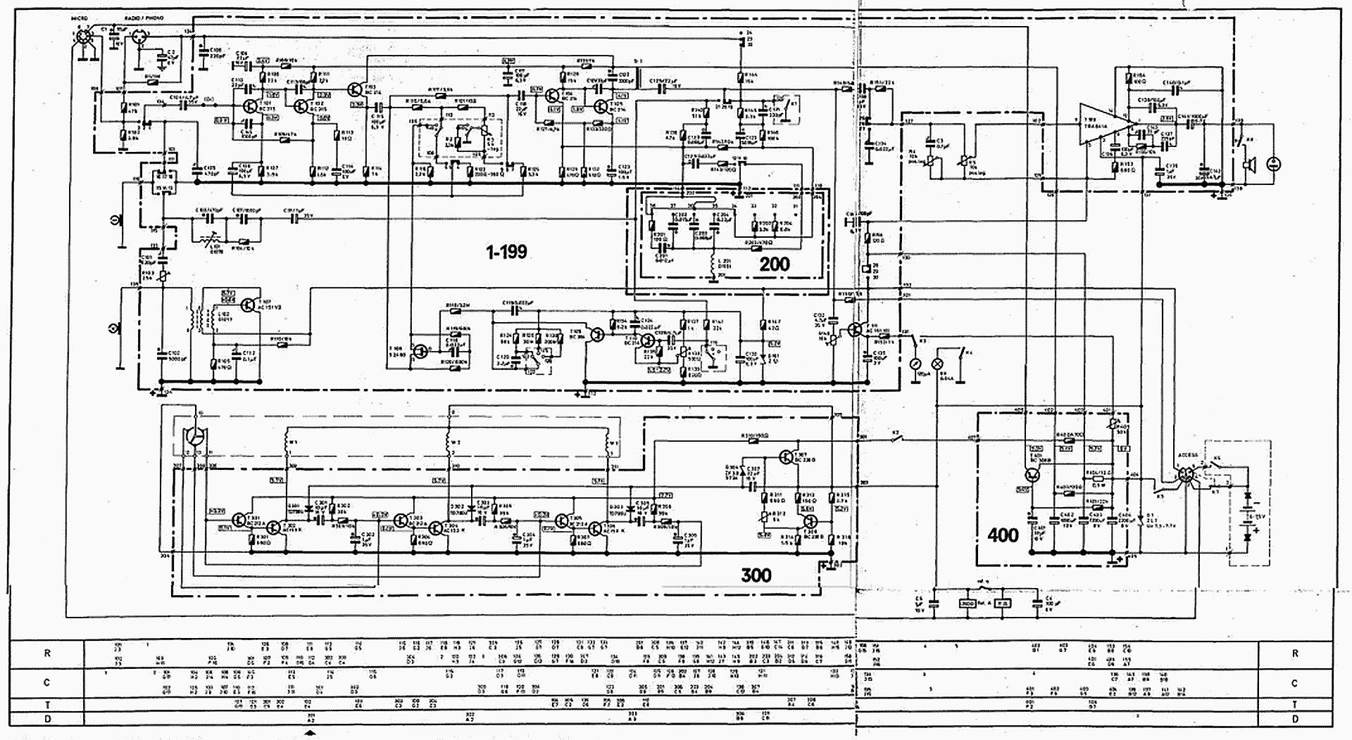
Hmmm... looks like there are schematics available: ><https://www.google.com/search?udm=2&q=uher%204000%20report%20monitor%20schematic>
This one looks like the 4000 Service Manual: ><https://www.yumpu.com/en/document/read/37747450/service-manual-uher-report-4000-ic>
I'm not sure if they want personal info, money, or both. Looks like
it's all there, but difficult to read. I made a screenshot and did
some image enhancement. Not great, but maybe good enough: ><https://www.learnbydestroying.com/jeffl/crud/Uher%20Report%204000%20IC%20Schematic.jpg>
Likewise, the EBC voltage differences in the amp
chain were all pretty much as expected - but not so with the devices
in the AGC. I believe it's the AGC but I've gone as far as I can and
am ready to farm this out!
That's a very important and obvious clue. In the distant past, I
would model the affected are using LTSpice. I'm not sure I could do
that today with QSpice. These days, asking someone measure audio
levels for you should be is easier:
<https://www.tapeheads.net>
<https://www.youtube.com/watch?v=Ac3cXu27M-M>
All solid advice, Jeff; but all already tried. I'm gonna send this
mo-fo out for a special service and let the experts deal with it as
there is probably quite a lot of re-alignment required too, the
bastard.
Methinks you give up too easily. Maybe wait a few days, and come back
to the problem with some fresh ideas.
... Time for someone else more experienced with Uhers to take over
methinks.
Cursitor Doom <cd6699@notformail.com> wrote:
... Time for someone else more experienced with Uhers to take over
methinks.
I used to repair them many years ago. if you live anywhere near Bath,
drop in and I'll try to help you.
On Fri, 28 Nov 2025 11:37:56 +0000, liz@poppyrecords.invalid.invalid
(Liz Tuddenham) wrote:
Cursitor Doom <cd6699@notformail.com> wrote:
... Time for someone else more experienced with Uhers to take over
methinks.
I used to repair them many years ago. if you live anywhere near Bath,
drop in and I'll try to help you.
That's very good of you and I would - but unfortunately I left the UK
many years ago. Thanks, anyway. :)
Jeff, it's a Uher Report Monitor 4000 so mono only. ...
Cursitor Doom schrieb:
[...]
Jeff, it's a Uher Report Monitor 4000 so mono only. ...
<https://elektrotanya.com/showresult?what=uher+report+monitor+4000&kategoria=All&kat2=All>
This one?
HTH
Reinhard
On Sat, 29 Nov 2025 00:44:27 +0100, Reinhard Zwirner <reinhard.zwirner@t-online.de> wrote:
Cursitor Doom schrieb:
[...]
Jeff, it's a Uher Report Monitor 4000 so mono only. ...
<https://elektrotanya.com/showresult?what=uher+report+monitor+4000&kategoria=All&kat2=All>
This one?
HTH
Reinhard
Nice. I couldn't find any schematics in the above download. ...
Cursitor Doom schrieb:
[...]
Jeff, it's a Uher Report Monitor 4000 so mono only. ...
<https://elektrotanya.com/showresult?what=uher+report+monitor+4000&kategoria=All&kat2=All>
This one?
Cursitor Doom <cd6699@notformail.com> wrote:
On Fri, 28 Nov 2025 11:37:56 +0000, liz@poppyrecords.invalid.invalid
(Liz Tuddenham) wrote:
Cursitor Doom <cd6699@notformail.com> wrote:
... Time for someone else more experienced with Uhers to take over
methinks.
I used to repair them many years ago. if you live anywhere near Bath,
drop in and I'll try to help you.
That's very good of you and I would - but unfortunately I left the UK
many years ago. Thanks, anyway. :)
I'm sure I had the circuit diagrams for several of the Uher models - but
i have no idea where they are now.
I seem to remember the 2-transistor mic pre-amps had a rather clever >counter-intuitive volume control arrangement, which gave a wide range of >possible volume input levels. The wiper was connected to the output of
the second transistor, with one end of the track going to the followiong >stage and the other end going to the emitter of the first transistor.
As the volume was turned down it increased the negative feedback around
the front end.
If you suspect the fault is in the AGC system, do you get an improvement
if you switch the AGC off?
On Sat, 29 Nov 2025 00:44:27 +0100, Reinhard Zwirner <reinhard.zwirner@t-online.de> wrote:
Cursitor Doom schrieb:
[...]
Jeff, it's a Uher Report Monitor 4000 so mono only. ...
<https://elektrotanya.com/showresult?what=uher+report+monitor+4000&kategoria=All&kat2=All>
This one?
That's the machine, yes. But there's no schematics in this one.
Cursitor Doom schrieb:
On Sat, 29 Nov 2025 00:44:27 +0100, Reinhard Zwirner
<reinhard.zwirner@t-online.de> wrote:
Cursitor Doom schrieb:
[...]
Jeff, it's a Uher Report Monitor 4000 so mono only. ...
<https://elektrotanya.com/showresult?what=uher+report+monitor+4000&kategoria=All&kat2=All>
This one?
That's the machine, yes. But there's no schematics in this one.
But you'll find it in my other post.
On Tue, 25 Nov 2025 11:43:50 -0500, legg <legg@nospam.magma.ca> wrote:
On Sun, 23 Nov 2025 22:58:42 +0000, Cursitor Doom
<cd6699@notformail.com> wrote:
I've been trying to trace an issue with a Uher tape deck in respect of
extremely low audio gain during recording. I was delighted when I
spotted a resistor in the AGC section with a tiny blow-hole half way
down its body. I was able to confirm this when I removed it for
examination under a stereoscope. There was even a bulge under the hole
where some pressure had clearly built-up immediately prior to the
blow.'Easy fix!' I thought; 5 minutes and it's done. However, I was
baffled when it tested spot-on its 1200 intended ohms! WTF?? Something
must have pulled excess current through that component and the obvious
culprit was the BJT it was the series resistor for. However, once
again, it tested fine! I just never have encountered an outcome like
that before. Anyone had similar?
CD
Mfring defect in the epoxy 'paint' finish.
Unless something upstream that caused an over-current went
open-circuit before the resistor could totally fail?
On 2025-11-25 14:50, Cursitor Doom wrote:
On Tue, 25 Nov 2025 11:43:50 -0500, legg <legg@nospam.magma.ca> wrote:
On Sun, 23 Nov 2025 22:58:42 +0000, Cursitor Doom
<cd6699@notformail.com> wrote:
I've been trying to trace an issue with a Uher tape deck in respect of >>>> extremely low audio gain during recording. I was delighted when I
spotted a resistor in the AGC section with a tiny blow-hole half way
down its body. I was able to confirm this when I removed it for
examination under a stereoscope. There was even a bulge under the hole >>>> where some pressure had clearly built-up immediately prior to the
blow.'Easy fix!' I thought; 5 minutes and it's done. However, I was
baffled when it tested spot-on its 1200 intended ohms! WTF?? Something >>>> must have pulled excess current through that component and the obvious >>>> culprit was the BJT it was the series resistor for. However, once
again, it tested fine! I just never have encountered an outcome like
that before. Anyone had similar?
CD
Mfring defect in the epoxy 'paint' finish.
Unless something upstream that caused an over-current went
open-circuit before the resistor could totally fail?
The coating is cross-linked, so it chars rather than melting. If you
ablate the resistive film with some huge overload, it just cracks off
the coating as it goes.
Cheers
Phil Hobbs
On Sat, 29 Nov 2025 14:01:43 +0100, Reinhard Zwirner <reinhard.zwirner@t-online.de> wrote:
Cursitor Doom schrieb:
On Sat, 29 Nov 2025 00:44:27 +0100, Reinhard Zwirner
<reinhard.zwirner@t-online.de> wrote:
Cursitor Doom schrieb:
[...]
Jeff, it's a Uher Report Monitor 4000 so mono only. ...
<https://elektrotanya.com/showresult?what=uher+report+monitor+4000&kategoria=All&kat2=All>
This one?
That's the machine, yes. But there's no schematics in this one.
But you'll find it in my other post.
I already had that one from RM, Reinhardt. Plus I also have a hard
copy service manual with a large scale schematic of another close
variant of this model. Unfortunately, neither of these totally
correspond to the 4000 I have here and the AGC section is *totally*
different from either schematic. :(
Cursitor Doom schrieb:
On Sat, 29 Nov 2025 14:01:43 +0100, Reinhard Zwirner
<reinhard.zwirner@t-online.de> wrote:
Cursitor Doom schrieb:
On Sat, 29 Nov 2025 00:44:27 +0100, Reinhard Zwirner
<reinhard.zwirner@t-online.de> wrote:
Cursitor Doom schrieb:
[...]
Jeff, it's a Uher Report Monitor 4000 so mono only. ...
<https://elektrotanya.com/showresult?what=uher+report+monitor+4000&kategoria=All&kat2=All>
This one?
That's the machine, yes. But there's no schematics in this one.
But you'll find it in my other post.
I already had that one from RM, Reinhardt. Plus I also have a hard
copy service manual with a large scale schematic of another close
variant of this model. Unfortunately, neither of these totally
correspond to the 4000 I have here and the AGC section is *totally*
different from either schematic. :(
Did you try to compare the AGC circuits of types 4200 var1/2 (stereo,
2-track tape heads) and 4400 (stereo, 4-track tape heads) with the
AGC circuit of your device? Those three schematics can also be found
in RM.
Here are the photos of the suspicous resistor; let me know what you
think. In addition to the blow holes, it's also slightly mis-shapen.
https://disk.yandex.com/d/ommuYJD2ZKsW8A
Here are the photos of the suspicous resistor; let me know what you
think. In addition to the blow holes, it's also slightly mis-shapen.
https://disk.yandex.com/d/ommuYJD2ZKsW8A
On Sun, 30 Nov 2025 14:38:33 +0000, Cursitor Doom
<cd6699@notformail.com> wrote:
Here are the photos of the suspicous resistor; let me know what you
think. In addition to the blow holes, it's also slightly mis-shapen.
https://disk.yandex.com/d/ommuYJD2ZKsW8A
Doesn't look like a paint defect, nnless you've been poking
at it with an exacto knife tip, after the fact.
Can't tell if it's smoke or just bad shadowing. Why not same
exposure and lighting in all three images?
On Sun, 30 Nov 2025 14:38:33 +0000, Cursitor Doom
<cd6699@notformail.com> wrote:
Here are the photos of the suspicous resistor; let me know what you
think. In addition to the blow holes, it's also slightly mis-shapen.
https://disk.yandex.com/d/ommuYJD2ZKsW8A
<https://disk.yandex.com/d/ommuYJD2ZKsW8A/DSC_0758.JPG>
I can't tell if the black area above the hole is a burn mark or a
shadow from the lower end of the resistor. There are no additional
burn marks along the perimeter of the hole which suggests that
overheating was not the cause. If it were a volcanic explosion or
burn mark caused by overheating, I would expect to see black carbon
around the inside of the hole. Instead, it looks like clean ceramic >(coating) in the hole.
That could also have been caused by a bubble
in the coating produced during manufacture. I believe you mentioned
that the resistor survived and reads the correct 1200 ohms, which
favor the bubble explanation. If the carbon film resistor had been >overheated, it would have changed value greater than +/-5%.
Can you provide better photos of just the hole area (without shadows)
Hint, use a microscope ><https://www.learnbydestroying.com/jeffl/pics/microscopes/Olympus%20SZ30/SZ30-01.jpg>
and fix your lighting so that you don't have any shadows. I sometimes
get lazy when working with small parts and just use two flashlights.
Jeff Liebermann schrieb:
On Sat, 29 Nov 2025 00:44:27 +0100, Reinhard Zwirner
<reinhard.zwirner@t-online.de> wrote:
Cursitor Doom schrieb:
[...]
Jeff, it's a Uher Report Monitor 4000 so mono only. ...
<https://elektrotanya.com/showresult?what=uher+report+monitor+4000&kategoria=All&kat2=All>
This one?
HTH
Reinhard
Nice. I couldn't find any schematics in the above download. ...
Sorry. Instead, give this a try: ><https://www.radiomuseum.org/r/uher_report_4000_monitor.html>
HTreallyH
Reinhard
I have a stereocope and two microscopes,
but they're not the type you
can easily take photos through. I really must order something more
suitable for this purpose, because the stereo I have is old-school
analog a bit like yours.
On Sun, 30 Nov 2025 18:16:59 +0000, Cursitor Doom
<cd6699@notformail.com> wrote:
I have a stereocope and two microscopes,
I have about seven microscopes. Three of them work. The remaining
four need repair. One can never had enough microscopes.
but they're not the type you
can easily take photos through. I really must order something more
suitable for this purpose, because the stereo I have is old-school
analog a bit like yours.
<https://www.learnbydestroying.com/jeffl/pics/microscopes/>
I have three more that are not among the photos.
Trinocular head perhaps? Note the 3rd eyepiece for the camera: ><https://www.google.com/search?udm=2&q=trinocular%20vision%20microscope>
You don't need a trinocular head. When I need to take photos on a
binocular microscope, I remove one of the eyepieces, insert 0.5x lens,
add a camera lens adapter, and take photos. Your binocular microscope
should work: ><https://www.google.com/search?q=microscope%20camera%20adapter&udm=2>
For illumination, I use a cheap LED ring light: ><https://www.google.com/search?udm=2&q=microscope%20LED%20ring%20light>
If I need more light, I have various flashlights lights and mounting >contraptions.
On Sun, 30 Nov 2025 12:41:35 -0500, legg <legg@nospam.magma.ca> wrote:
On Sun, 30 Nov 2025 14:38:33 +0000, Cursitor Doom
<cd6699@notformail.com> wrote:
Here are the photos of the suspicous resistor; let me know what you >>>think. In addition to the blow holes, it's also slightly mis-shapen.
https://disk.yandex.com/d/ommuYJD2ZKsW8A
Doesn't look like a paint defect, nnless you've been poking
at it with an exacto knife tip, after the fact.
I've not been excavating! There was a bubble on the surface
originally, which I scraped off with a fingernail to reveal that hole.
I didn't dig any further.
Can't tell if it's smoke or just bad shadowing. Why not same
exposure and lighting in all three images?
It was very difficult to photograph, because the depth of field was
close to zero and the resistor was only millimeters from the lens
glass. I had to use a hand-held LED lamp for illumination, but
full-on, frontal illumination wasn't possible due to the proximity of
the subject to the lens, I'm afraid. The lighting varies because I was >holding the lamp by hand each time.
On Fri, 28 Nov 2025 19:05:31 +0000, liz@poppyrecords.invalid.invalid
(Liz Tuddenham) wrote:
Cursitor Doom <cd6699@notformail.com> wrote:
On Fri, 28 Nov 2025 11:37:56 +0000, liz@poppyrecords.invalid.invalid
(Liz Tuddenham) wrote:
Cursitor Doom <cd6699@notformail.com> wrote:
... Time for someone else more experienced with Uhers to take over
methinks.
I used to repair them many years ago. if you live anywhere near Bath,
drop in and I'll try to help you.
That's very good of you and I would - but unfortunately I left the UK
many years ago. Thanks, anyway. :)
I'm sure I had the circuit diagrams for several of the Uher models - but
i have no idea where they are now.
I seem to remember the 2-transistor mic pre-amps had a rather clever >>counter-intuitive volume control arrangement, which gave a wide range of >>possible volume input levels. The wiper was connected to the output of
the second transistor, with one end of the track going to the followiong >>stage and the other end going to the emitter of the first transistor.
As the volume was turned down it increased the negative feedback around
the front end.
If you suspect the fault is in the AGC system, do you get an improvement
if you switch the AGC off?
Doesn't bring the audio back, I'm afraid. However, that doesn't
exculpate the AGC, as they've embedded the on/oiff/fast/slow switch
right in the middle of the stage.
On Sun, 30 Nov 2025 18:07:46 +0000, Cursitor Doom
<cd6699@notformail.com> wrote:
On Sun, 30 Nov 2025 12:41:35 -0500, legg <legg@nospam.magma.ca> wrote:
On Sun, 30 Nov 2025 14:38:33 +0000, Cursitor Doom
<cd6699@notformail.com> wrote:
Here are the photos of the suspicous resistor; let me know what you >>>>think. In addition to the blow holes, it's also slightly mis-shapen.
https://disk.yandex.com/d/ommuYJD2ZKsW8A
Doesn't look like a paint defect, nnless you've been poking
at it with an exacto knife tip, after the fact.
I've not been excavating! There was a bubble on the surface
originally, which I scraped off with a fingernail to reveal that hole.
I didn't dig any further.
Can't tell if it's smoke or just bad shadowing. Why not same
exposure and lighting in all three images?
It was very difficult to photograph, because the depth of field was
close to zero and the resistor was only millimeters from the lens
glass. I had to use a hand-held LED lamp for illumination, but
full-on, frontal illumination wasn't possible due to the proximity of
the subject to the lens, I'm afraid. The lighting varies because I was >>holding the lamp by hand each time.
A 'bubble' is a definite sign of a paint defect at time of mfr..
On Sat, 29 Nov 2025 12:47:21 +0000, Cursitor Doom
<cd6699@notformail.com> wrote:
On Fri, 28 Nov 2025 19:05:31 +0000, liz@poppyrecords.invalid.invalid
(Liz Tuddenham) wrote:
Cursitor Doom <cd6699@notformail.com> wrote:
On Fri, 28 Nov 2025 11:37:56 +0000, liz@poppyrecords.invalid.invalid
(Liz Tuddenham) wrote:
Cursitor Doom <cd6699@notformail.com> wrote:
... Time for someone else more experienced with Uhers to take over
methinks.
I used to repair them many years ago. if you live anywhere near Bath, >>>> >drop in and I'll try to help you.
That's very good of you and I would - but unfortunately I left the UK
many years ago. Thanks, anyway. :)
I'm sure I had the circuit diagrams for several of the Uher models - but >>>i have no idea where they are now.
I seem to remember the 2-transistor mic pre-amps had a rather clever >>>counter-intuitive volume control arrangement, which gave a wide range of >>>possible volume input levels. The wiper was connected to the output of >>>the second transistor, with one end of the track going to the followiong >>>stage and the other end going to the emitter of the first transistor.
As the volume was turned down it increased the negative feedback around >>>the front end.
If you suspect the fault is in the AGC system, do you get an improvement >>>if you switch the AGC off?
Doesn't bring the audio back, I'm afraid. However, that doesn't
exculpate the AGC, as they've embedded the on/oiff/fast/slow switch
right in the middle of the stage.
Troubleshoot in the 'off' position and assume that AGC has nothing
to do with your problem.
RL
On Mon, 01 Dec 2025 08:01:18 -0500, legg <legg@nospam.magma.ca> wrote:
On Sun, 30 Nov 2025 18:07:46 +0000, Cursitor Doom
<cd6699@notformail.com> wrote:
On Sun, 30 Nov 2025 12:41:35 -0500, legg <legg@nospam.magma.ca> wrote:
On Sun, 30 Nov 2025 14:38:33 +0000, Cursitor Doom >>>><cd6699@notformail.com> wrote:
Here are the photos of the suspicous resistor; let me know what you >>>>>think. In addition to the blow holes, it's also slightly mis-shapen.
https://disk.yandex.com/d/ommuYJD2ZKsW8A
Doesn't look like a paint defect, nnless you've been poking
at it with an exacto knife tip, after the fact.
I've not been excavating! There was a bubble on the surface
originally, which I scraped off with a fingernail to reveal that hole.
I didn't dig any further.
Can't tell if it's smoke or just bad shadowing. Why not same
exposure and lighting in all three images?
It was very difficult to photograph, because the depth of field was
close to zero and the resistor was only millimeters from the lens
glass. I had to use a hand-held LED lamp for illumination, but
full-on, frontal illumination wasn't possible due to the proximity of
the subject to the lens, I'm afraid. The lighting varies because I was >>>holding the lamp by hand each time.
A 'bubble' is a definite sign of a paint defect at time of mfr..
I've never come across that before; just assumed it had blown through >over-current. I was *convinced* I was really on to something. I
suppose I could excavate the hole out and see how far down it goes
down. I might do that tomorrow just out of idle curiosity.
He said, "Give the heads a good clean,
then." I said, "They don't look dirty." He said, "Give 'em a good
clean anyway and see if that fixes it." So I did (not having any faith
it would help in the least, however). Nevertheless, full recording was instantly restored!
Cursitor Doom <cd6699@notformail.com> wrote:
[...]
He said, "Give the heads a good clean,
then." I said, "They don't look dirty." He said, "Give 'em a good
clean anyway and see if that fixes it." So I did (not having any faith
it would help in the least, however). Nevertheless, full recording was
instantly restored!
I asked if you had cleaned the heads right at the beginning of this
thread. The tineiest of gaps between the head and the tape can have
quite drastic effects on reproduction and even worse ones on recording.
Another cause of those symptoms, which is sometimes discovered by
complete beginners, is having the tape twisted so they are trying to
record or play though the backing material. Some tapes that have
'bootlaced' can have an entire twisted section in the middle of an
otherwise right-way-around tape. I have also seen spillages due to
putting the spools on upside down, so they unwound under power instead
of winding up.
The most confusing decks of all are those with non-standard tape paths
and winding systems. One Truvox deck ran the tape from right to left
and several early machines had anticlockwise takeup spools that wound
the tape oxide-outwards.
On Wed, 10 Dec 2025 21:58:21 +0000, liz@poppyrecords.invalid.invalid
(Liz Tuddenham) wrote:
Cursitor Doom <cd6699@notformail.com> wrote:
[...]
He said, "Give the heads a good clean,
then." I said, "They don't look dirty." He said, "Give 'em a good
clean anyway and see if that fixes it." So I did (not having any faith
it would help in the least, however). Nevertheless, full recording was
instantly restored!
I asked if you had cleaned the heads right at the beginning of this
thread. The tineiest of gaps between the head and the tape can have
quite drastic effects on reproduction and even worse ones on recording.
I'm not seeing it for some reason. Can you give me the message ID?
Cursitor Doom <cd6699@notformail.com> wrote:
I've been trying to trace an issue with a Uher tape deck in respect of
extremely low audio gain during recording. I was delighted when I
spotted a resistor in the AGC section with a tiny blow-hole half way
down its body. I was able to confirm this when I removed it for
examination under a stereoscope. There was even a bulge under the hole
where some pressure had clearly built-up immediately prior to the
blow.'Easy fix!' I thought; 5 minutes and it's done. However, I was
baffled when it tested spot-on its 1200 intended ohms! WTF?? Something
must have pulled excess current through that component and the obvious
culprit was the BJT it was the series resistor for. However, once
again, it tested fine! I just never have encountered an outcome like
that before. Anyone had similar?
Have you cleaned the tape heads?
Another cause of those symptoms, which is sometimes discovered by
complete beginners, is having the tape twisted so they are trying to
record or play though the backing material. Some tapes that have
'bootlaced' can have an entire twisted section in the middle of an
otherwise right-way-around tape. I have also seen spillages due to
putting the spools on upside down, so they unwound under power instead
of winding up.
The most confusing decks of all are those with non-standard tape paths
and winding systems. One Truvox deck ran the tape from right to left
and several early machines had anticlockwise takeup spools that wound
the tape oxide-outwards.
Cursitor Doom <cd6699@notformail.com> wrote:
Just goes to show how a
tiny bit of invisible foulage can throw a real spanner in the works
for the unwary. Lesson learned!
About 6 months ago I was asked by a local dancing school if I still had
the master tape of a show where I had done the sound 20 years ago.
After spending an evening sorting through piles of tapes stored in a
disused lavatory (Yes, really!) we found it. I laced it up on one of my
Ferrographs (Logic 7) and the sound quality immediately deteriorated to
rubbish.
Knowing what I now know and never having handled 40+ year old tapes
before, I can well believe it. The F'graph I recently had serviced is
a Logic 7 as well, BTW.
I bought one that the BBC had scrapped because of a "Logic fault"
(according to the ticket tied to it). The problem was a very mysterious >intermittent one: sometimes pressing one button would give the function
of a different button - but sometimes it worked correctly. I kept a
note of the faults when they showed up and was lucky enough to obtain a
full service manual that had a table of logic faults included with it.
The table showed that the fault was coming from one of the relays not >operating - but when I watched carefully I could see the relay armature >moved. If I operated it by hand, everthing worked correctly.
Then I spotted the cause: a tiny iron filing was in the air gap -
sometimes the magnetism caused it to stand up on end, preventing the
full travel of the armature - but sometimes it lay down flat and
everything worked correctly. I removed it with a bit of adhesive tape
and was pleased to find I had bought an excellent machine in perfect >condition at a ridiculously low price.
We played the tape for long enough to identify that it was the correct
one, then I had to spend the following evening cleaning up the required
5-minute segment. I wound the of tape backwards and forwards through a
fold of soft cloth, picking up loads of debris at each pass.
According to the nerds on Tapeheads, before we play an old tape we
should bake it beforehand - yes, really - and digitize it upon first
play then bin it for the sake of our machines!
It depends on the cause of the problem. That is the recommended way of >treating 'sticky shed' but if the tape is very old (and sticky shed
isn't the problem), baking it may cause it to become brittle and keep >snapping.
Eventually i was able to play it, stopping and cleaning the heads and
the guides several times. If you don't clean the guides as well as all
the heads, including the erase head, even a clean tape can drag
particles into the recording and playback heads. Finally I edited the
good bits together, burnt them onto a CDR and sent them to the dancing
school.
Yes, you would have to do the entire visible/accessible tape transport
mechanism or it won't have the desired effect for that reason. I find
it unbelievable that heads that *appear* spotless can refuse to work
properly until freshly cleaned again. How many picograms of crap does
it take to mess things up? Can't be many!
I can't remember the exact reference but there were papers written on
this in the 1950s and 1960s. I would begin by looking in the Philips >Technical Review around the late 1950s and onwards. It became even more >important when tape was first used for digital and video recording
because it affects the high frequencies much worse than the low
frequencies.
A 'bubble' is a definite sign of a paint defect at time of mfr..
I've never come across that before; just assumed it had blown through >>over-current. I was *convinced* I was really on to something. I
suppose I could excavate the hole out and see how far down it goes
down. I might do that tomorrow just out of idle curiosity.
Well, before I got around to that, my Ferrograph, which had just got
back from a *very* expensive refurb, presented with the exact same
problem: zero recording to tape despite plenty of audio input. Since
the F'graph was still under warranty from the servicing people, I
called them up and complained (politely - fortunately, as it
happened). The chap on the phone said, "have you been playing old
tapes on it?" I said, "Yes." He said, "Give the heads a good clean,
then." I said, "They don't look dirty." He said, "Give 'em a good
clean anyway and see if that fixes it." So I did (not having any faith
it would help in the least, however). Nevertheless, full recording was >instantly restored! So I thought I'd try the same thing with the Uher
- and despite the heads looking perfectly clean, that worked too!
It's been nearly 50 years since I last used reel to reel tapes and it
seems I'd forgotten a basic piece of regular maintenance and that was
the cause of my problem. I'd spent *hours* going through all the
circuitry looking for anomalous voltage readings and finding none,
squirting test signals into the amp chain and not finding any red
flags there, not to mention the bias oscillator and the AGC. Whilst
all the time, the solution was a simple bit of housework.
Back in the day, we didn't need to worry about oxide-shedding, but old
tapes age the same as we do, it transpires; some worse than others.
Ampex are the *worst* in this respect, I've learned. Don't play old
Ampex. Don't buy NOS Ampex. Google "sticky shed" for more info and
don't fall into the same rabbit hole I did!
I bought mine for an absurdly low price at an auction of house
contents (just over a hundred quid) - but spent almost ten times that
amount on putting it back to original specification. ...
Well, it's all new to me having to deal with vintage tape. Back in the
day, the tapes we had were still young and fresh and this issue simply
never arose (not in my personal experience at any rate). My serviceman reckons it's a good idea to use IPA intially, then polish the heads
with Autosol to get rid of any invisible remaining residue and it's an approach I now plan to stick to in future!
Cursitor Doom <cd6699@notformail.com> wrote:
[...]
[Ferrograph Logic 7]
I bought mine for an absurdly low price at an auction of house
contents (just over a hundred quid) - but spent almost ten times that
amount on putting it back to original specification. ...
Mine came from a scrapyard in the days when the BBC disposed of their >unwanted gear by that route. I invested in a copy of the full sevice
manual, which meant I could do all the repairs and servicing myself. I
was doing transfers from discs for the UK National Sound Archive and had
to meet their specifications: every tape had to begin with a set of
line-up tones to confirm that the azimuth and speed were spot-on and the
bias settings and equalisation were correct for that particular reel of
tape. If the playback wasn't within their specified limits, the tape
came back and I had to do the whole job again (and didn't get paid until
it was satisfactory).
Other transcriptors rather looked down on the Ferrographs as being
dated, clunky battleships (one commented "You could play a length of
bicycle chain on that thing!"), but I found they had been designed by
people who actually had to use them professionally in arduous
conditions, not by salesmen in plush showrooms. A tape path that looked
so easy to thread in some other machines turned ito a contortionist's >nightmare when it came to fast cut-and-splice editing because parts of
the swish-looking casing got in the way of the tape when you needed to
lift it out of the heads. The Ferrograph *was* clunky - and all the
better for it.
[...]
Well, it's all new to me having to deal with vintage tape. Back in the
day, the tapes we had were still young and fresh and this issue simply
never arose (not in my personal experience at any rate). My serviceman
reckons it's a good idea to use IPA intially, then polish the heads
with Autosol to get rid of any invisible remaining residue and it's an
approach I now plan to stick to in future!
Try not to leave the IPA on the pinch wheel for any length of time, as I
have heard it can harden the rubber. If the pinch wheel tyre ever
starts to go badly wrong (e.g. mushy), you can get away with cutting the >rubber off and stacking 3 'O'-rings on the metal core until such time
as you can get a proper replacement. Don't get the mush on your skin,
it is dangerous.
I have never used Auto-Sol on the heads but I imagine it would be very >effective - possibly a little too effective for anything other than >occasional use in extreme circumstances.
I had no idea you were so experienced and
venerable in this field.
I can barely lift my L7 these days; not getting any younger. As you
say, they're built like tanks. Not sure where they fit in the fidelity pantheon of high-end tape players. Some say better than Revox and the
Swiss machines, others say not even close. But build-wise, they're
virtually indestructible.
Ferrograph fucked up badly at some point in their history as you no
doubt know by using some weird compound on their pinch wheels which
turned into a thick black gum which proceeded to jam the works up and
make the most awful and hard to remove mess inside all the moving
parts.
The "dangerous mush" - would that be rich in hydrofluoric acid,
perchance?
I have never used Auto-Sol on the heads but I imagine it would be very >effective - possibly a little too effective for anything other than >occasional use in extreme circumstances.
It's a very mild abrasive akin to toothpaste. My servicer has been
doing F'graphs for almost 60 years now and recommends it, so I think
you'll find it's safe enough!
On 12/10/2025 6:14 PM, Cursitor Doom wrote:
On Wed, 10 Dec 2025 21:58:21 +0000, liz@poppyrecords.invalid.invalid
(Liz Tuddenham) wrote:
Cursitor Doom <cd6699@notformail.com> wrote:
[...]
He said, "Give the heads a good clean,
then." I said, "They don't look dirty." He said, "Give 'em a good
clean anyway and see if that fixes it." So I did (not having any faith >>>> it would help in the least, however). Nevertheless, full recording was >>>> instantly restored!
I asked if you had cleaned the heads right at the beginning of this
thread. The tineiest of gaps between the head and the tape can have
quite drastic effects on reproduction and even worse ones on recording.
I'm not seeing it for some reason. Can you give me the message ID?
On Wed, 26 Nov 2025 09:55:24 +0000, liz@poppyrecords.invalid.invalid
(Liz Tuddenham) wrote:
Cursitor Doom <cd6699@notformail.com> wrote:
I've been trying to trace an issue with a Uher tape deck in respect of
extremely low audio gain during recording. I was delighted when I
spotted a resistor in the AGC section with a tiny blow-hole half way
down its body. I was able to confirm this when I removed it for
examination under a stereoscope. There was even a bulge under the hole
where some pressure had clearly built-up immediately prior to the
blow.'Easy fix!' I thought; 5 minutes and it's done. However, I was
baffled when it tested spot-on its 1200 intended ohms! WTF?? Something
must have pulled excess current through that component and the obvious
culprit was the BJT it was the series resistor for. However, once
again, it tested fine! I just never have encountered an outcome like
that before. Anyone had similar?
Have you cleaned the tape heads?
Yes, but not for that reason as the fault just suddenly manifested out
of nowhere.
Another cause of those symptoms, which is sometimes discovered by
complete beginners, is having the tape twisted so they are trying to
record or play though the backing material. Some tapes that have
'bootlaced' can have an entire twisted section in the middle of an
otherwise right-way-around tape. I have also seen spillages due to
putting the spools on upside down, so they unwound under power instead
of winding up.
The most confusing decks of all are those with non-standard tape paths
and winding systems. One Truvox deck ran the tape from right to left
and several early machines had anticlockwise takeup spools that wound
the tape oxide-outwards.
On Wed, 10 Dec 2025 21:38:18 -0500, ehsjr <ehsjr@verizon.net> wrote:
On 12/10/2025 6:14 PM, Cursitor Doom wrote:
On Wed, 10 Dec 2025 21:58:21 +0000, liz@poppyrecords.invalid.invalid
(Liz Tuddenham) wrote:
Cursitor Doom <cd6699@notformail.com> wrote:I'm not seeing it for some reason. Can you give me the message ID?
[...]
He said, "Give the heads a good clean,
then." I said, "They don't look dirty." He said, "Give 'em a good
clean anyway and see if that fixes it." So I did (not having any faith >>>> it would help in the least, however). Nevertheless, full recording was >>>> instantly restored!
I asked if you had cleaned the heads right at the beginning of this
thread. The tineiest of gaps between the head and the tape can have
quite drastic effects on reproduction and even worse ones on recording. >>
On Wed, 26 Nov 2025 09:55:24 +0000, liz@poppyrecords.invalid.invalid
(Liz Tuddenham) wrote:
Cursitor Doom <cd6699@notformail.com> wrote:
I've been trying to trace an issue with a Uher tape deck in respect of >> extremely low audio gain during recording. I was delighted when I
spotted a resistor in the AGC section with a tiny blow-hole half way
down its body. I was able to confirm this when I removed it for
examination under a stereoscope. There was even a bulge under the hole >> where some pressure had clearly built-up immediately prior to the
blow.'Easy fix!' I thought; 5 minutes and it's done. However, I was
baffled when it tested spot-on its 1200 intended ohms! WTF?? Something >> must have pulled excess current through that component and the obvious >> culprit was the BJT it was the series resistor for. However, once
again, it tested fine! I just never have encountered an outcome like
that before. Anyone had similar?
Have you cleaned the tape heads?
Yes, but not for that reason as the fault just suddenly manifested out
of nowhere.
Much oblig'd. Clearly what happened here is that in the pile of old
tapes I was working through, there was a section of tape that was
shedding oxide (very common with old tapes) which undid all the prior cleaning effort. I did mention subsequently that when I tried the
suggestion from the Ferrograph guy I was expecting no positive outcome
as the heads *appeared* perfectly clean to me. Just goes to show how a
tiny bit of invisible foulage can throw a real spanner in the works
for the unwary. Lesson learned!
Cursitor Doom <cd6699@notformail.com> wrote:
On Wed, 10 Dec 2025 21:38:18 -0500, ehsjr <ehsjr@verizon.net> wrote:
On 12/10/2025 6:14 PM, Cursitor Doom wrote:
On Wed, 10 Dec 2025 21:58:21 +0000, liz@poppyrecords.invalid.invalid
(Liz Tuddenham) wrote:
Cursitor Doom <cd6699@notformail.com> wrote:I'm not seeing it for some reason. Can you give me the message ID?
[...]
He said, "Give the heads a good clean,
then." I said, "They don't look dirty." He said, "Give 'em a good
clean anyway and see if that fixes it." So I did (not having any faith >> >>>> it would help in the least, however). Nevertheless, full recording was >> >>>> instantly restored!
I asked if you had cleaned the heads right at the beginning of this
thread. The tineiest of gaps between the head and the tape can have
quite drastic effects on reproduction and even worse ones on recording. >> >>
On Wed, 26 Nov 2025 09:55:24 +0000, liz@poppyrecords.invalid.invalid
(Liz Tuddenham) wrote:
Cursitor Doom <cd6699@notformail.com> wrote:
I've been trying to trace an issue with a Uher tape deck in respect of >> > >> extremely low audio gain during recording. I was delighted when I
spotted a resistor in the AGC section with a tiny blow-hole half way
down its body. I was able to confirm this when I removed it for
examination under a stereoscope. There was even a bulge under the hole >> > >> where some pressure had clearly built-up immediately prior to the
blow.'Easy fix!' I thought; 5 minutes and it's done. However, I was
baffled when it tested spot-on its 1200 intended ohms! WTF?? Something >> > >> must have pulled excess current through that component and the obvious >> > >> culprit was the BJT it was the series resistor for. However, once
again, it tested fine! I just never have encountered an outcome like
that before. Anyone had similar?
Have you cleaned the tape heads?
Yes, but not for that reason as the fault just suddenly manifested out
of nowhere.
Much oblig'd. Clearly what happened here is that in the pile of old
tapes I was working through, there was a section of tape that was
shedding oxide (very common with old tapes) which undid all the prior
cleaning effort. I did mention subsequently that when I tried the
suggestion from the Ferrograph guy I was expecting no positive outcome
as the heads *appeared* perfectly clean to me. Just goes to show how a
tiny bit of invisible foulage can throw a real spanner in the works
for the unwary. Lesson learned!
About 6 months ago I was asked by a local dancing school if I still had
the master tape of a show where I had done the sound 20 years ago.
After spending an evening sorting through piles of tapes stored in a
disused lavatory (Yes, really!) we found it. I laced it up on one of my >Ferrographs (Logic 7) and the sound quality immediately deteriorated to >rubbish.
We played the tape for long enough to identify that it was the correct
one, then I had to spend the following evening cleaning up the required >5-minute segment. I wound the of tape backwards and forwards through a
fold of soft cloth, picking up loads of debris at each pass.
Eventually i was able to play it, stopping and cleaning the heads and
the guides several times. If you don't clean the guides as well as all
the heads, including the erase head, even a clean tape can drag
particles into the recording and playback heads. Finally I edited the
good bits together, burnt them onto a CDR and sent them to the dancing >school.
Just goes to show how a
tiny bit of invisible foulage can throw a real spanner in the works
for the unwary. Lesson learned!
About 6 months ago I was asked by a local dancing school if I still had
the master tape of a show where I had done the sound 20 years ago.
After spending an evening sorting through piles of tapes stored in a >disused lavatory (Yes, really!) we found it. I laced it up on one of my >Ferrographs (Logic 7) and the sound quality immediately deteriorated to >rubbish.
Knowing what I now know and never having handled 40+ year old tapes
before, I can well believe it. The F'graph I recently had serviced is
a Logic 7 as well, BTW.
We played the tape for long enough to identify that it was the correct
one, then I had to spend the following evening cleaning up the required >5-minute segment. I wound the of tape backwards and forwards through a >fold of soft cloth, picking up loads of debris at each pass.
According to the nerds on Tapeheads, before we play an old tape we
should bake it beforehand - yes, really - and digitize it upon first
play then bin it for the sake of our machines!
Eventually i was able to play it, stopping and cleaning the heads and
the guides several times. If you don't clean the guides as well as all
the heads, including the erase head, even a clean tape can drag
particles into the recording and playback heads. Finally I edited the
good bits together, burnt them onto a CDR and sent them to the dancing >school.
Yes, you would have to do the entire visible/accessible tape transport mechanism or it won't have the desired effect for that reason. I find
it unbelievable that heads that *appear* spotless can refuse to work
properly until freshly cleaned again. How many picograms of crap does
it take to mess things up? Can't be many!
| Sysop: | Amessyroom |
|---|---|
| Location: | Fayetteville, NC |
| Users: | 70 |
| Nodes: | 6 (0 / 6) |
| Uptime: | 00:35:07 |
| Calls: | 949 |
| Calls today: | 1 |
| Files: | 1,325 |
| Messages: | 281,479 |